S-4 interior photos
Torpedo Room
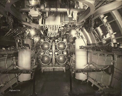
The large vertical tanks on each side store high pressure air for impulse firing of the torpedoes out of the tubes. The bracing sticking out from the hull on each side provided storage for up to ten torpedoes for reloads. The submarine carried a total of fourteen torpedoes. Four of them were in the tubes and ten in the room. Two each on each of the lower wider brackets and one each on the top shorter bracket.
U.S. Navy photo.
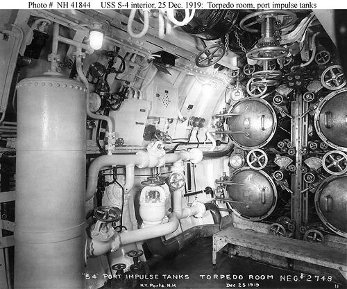
Note that the numbers 2 and 4 are on the torpedo tube doors. That means these are tubes # 2 and #4 . Tubes 1 and 3 are the starboard bank of tubes seen on the extreme right of the photo.
U.S. Navy photo.
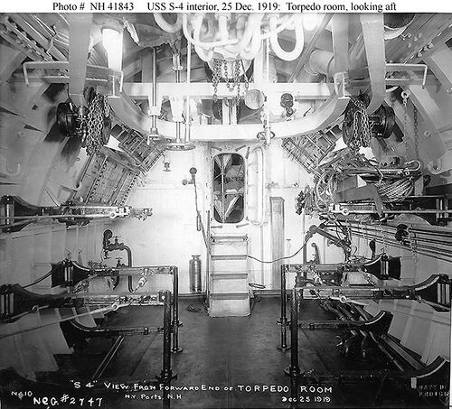
This view shows the torpedo storage racks more clearly. The submarine carried a total of fourteen torpedoes. Four of them were in the tubes and ten in the room. Two each on each of the lower wider brackets and one each on the top shorter bracket. Bunks can be seen tilted up in the after end of the room The torpedo loading skid can be seen on the top brace on the right side of the photo. Looking through the door into the battery/berthing compartment you can see crews berthing with the bunks "triced up".
U.S. Navy photo.
U.S. Navy photo.
Battery Compartment/Berthing
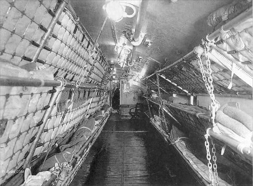
The bunks are triced up and have bedding on them, so this is an actively used compartment. In later years a cover was developed that contained the mattress and bedding and helped protect these combustible materials from burning in case of a flash fire. It is called a "flash cover" but they are missing from this image.
You can see the support cables and turnbuckles used to stabilize the bunk stanchions. They were suspended from the overhead since nothing was attached to the battery cover. If you look carefully, you can see the Christmas Bell hanging forward of the top far bunk and in line with the left door frame.
U.S. Navy photo.
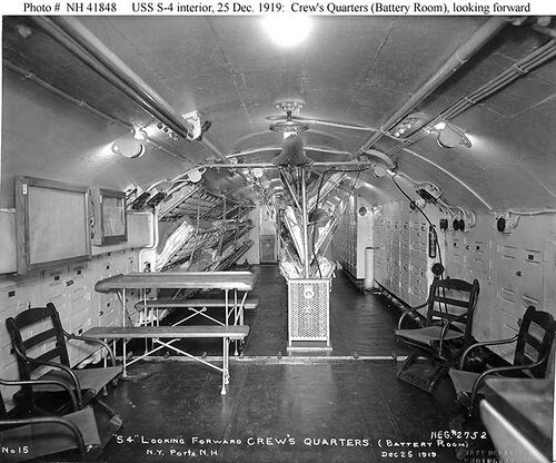
Nothing was attached to the deck since it was the cover for the battery. It consisted of removable planking covered with painted and shellacked canvas for waterproofing. Even though it looks like the heater is attached to the deck that is just a wooden pad to protect the canvas from the metal legs. The heater is portable not attached to the bunk stanchion. You can see the power cord snaking up to the overhead and down to a plug on the right. The bunks are all are braced by cables from the overhead to the foot of the stanchion to prevent sideways movement. A second space heater can be seen at the far end of the compartment and it looks to be bulkhead mounted.
The battery was made by Gould and was a Model 35-U. It was divided into two sections of 60 cells each. The total battery had a capacity of 1240 KWH. Just forward of the space heater you can see a light colored line going across the compartment. This is the divider bulkhead between the forward and aft sections of the battery.
The crew slept and ate in this compartment. The table to the left is just one of six fold up tables used for eating. When not in use they were folded up and stored at the aft end of the compartment. (see next photo) The chairs were for seating at the table as well as relaxing in. The rectangular ventilation duct work can be seen running a long the left side of the photo.
I'm told that the crews only head (toilet) was at the forward end of this compartment and was used by officers and enlisted alike.
U.S. Navy photo.
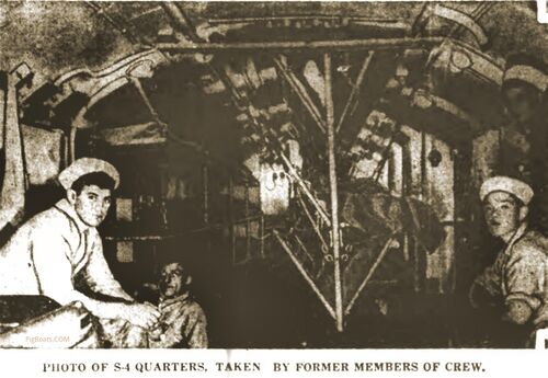
This photo was printed in a contemporary newspaper and identified as taken by former members of the crew.
Newspaper photo in the public domain.
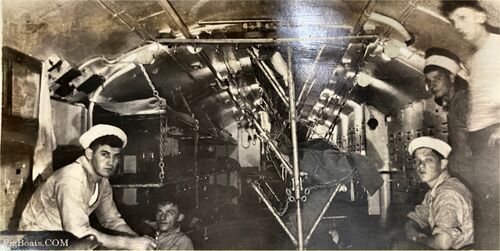
Flash from contributor's camera is seen at the top of the image. He did not want to be identified.
Photo from anonymous contributor in the private collection of Ric Hedman.
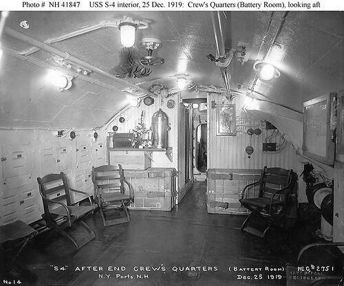
The ever-ready urn of coffee, life blood of the Navy, sits on the counter. A tiny Christmas tree sits on the counter next to it. The battery compartment ventilation fan is on the right side of the photo.
U.S. Navy photo.
Control Room
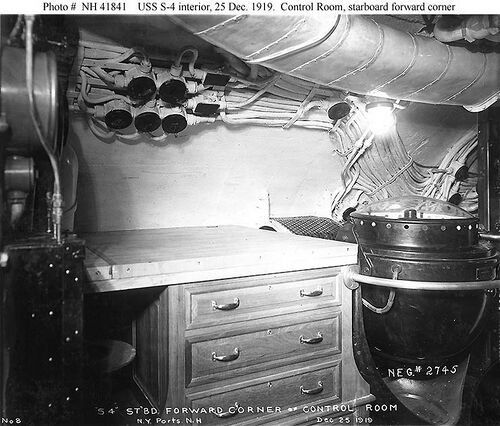
U.S. Navy photo.
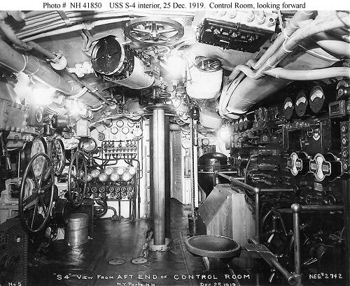
The electrical panels on the right are part of what later would be moved aft to an area known as the "maneuvering room". The electrical power to the motors was controlled from here. It wascalso from here that the current from the generators put a charge back into the battery during a battery charge. The "Controllerman" or "DC Electrician" sat at his station on the seat provided and operated the "sticks" as needed to carry out the propulsion requirements of the submarine.
The large motor in the center of the overhead is thought to be for raising and lowering the telescoping radio mast. The location is correct based on the observed drawings of this class of submarine.
U.S. Navy photo.
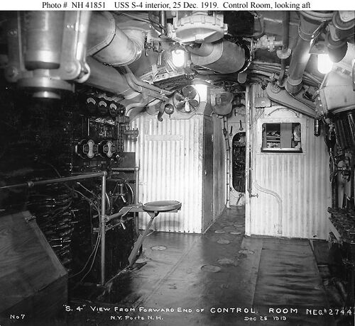
The two rooms with the corrugated sheet metal bulkheads are the radio room on the left and what most likely is the galley on the right. Through the door you can see the starboard diesel engine. The trim manifold is on the right side of the photo. The rheostat for controlling the trim pump is seen at the center of the photo edge.
U.S. Navy photo.
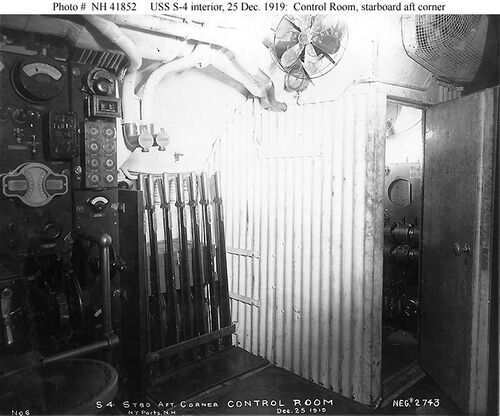
The door to the radio room is open and a small portion of the radio and its associated equipment can be seen. You can see that the door is quite thick so the room is probably well sound insulated so the radioman would have no problems hearing the signals.
U.S. Navy photo.
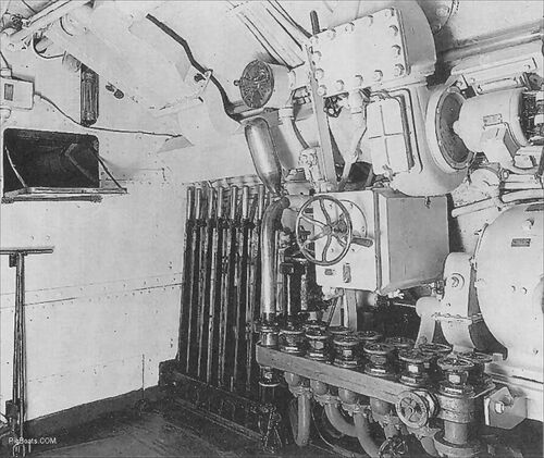
Seen on the bulkhead to the left is the drop-down serving window from the ship's galley.
U.S. Navy photo.
Engine Room
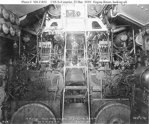
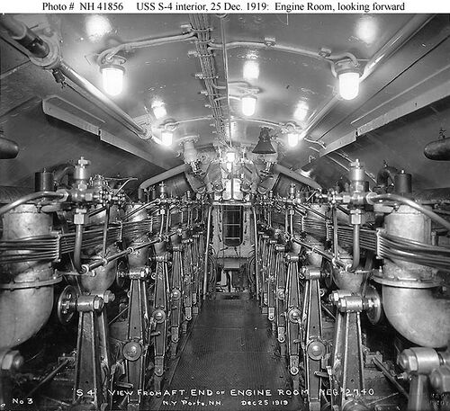
The two 700 HP NELSECO design MAN derivative 4-cycle diesel engines are seen filling the room either side of the center walkway. These engines were built from the NELSECO/MAN design at the Washington and Brooklyn Navy Yards. Although the Navy's experience with these engines was not perfect, they were at least better than the model installed in the EB design S-boats.
U.S. Navy photo.
U.S. Navy photo.
Motor Room
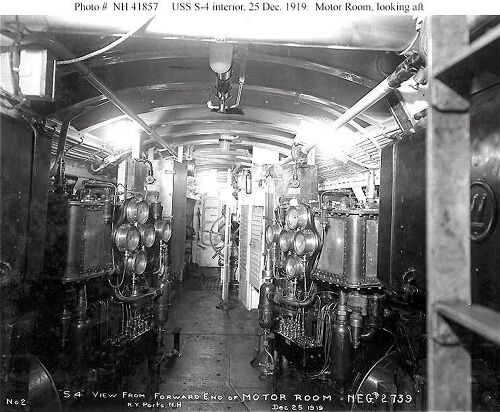
The ladder leads up to a deck hatch. In the overhead behind the ladder you can see the mechanical steering rod linkage heading aft to the tiller room.
U.S. Navy photo.
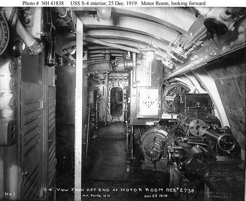
On the left the louvered doors for the shower and head can be seen.
The silvery vertical stripe seen off to the left in the foreground is the back side of a sight glass probably showing the fluid level of the aft trim tank, In the photo above you can see it from the front.
U.S. Navy photo.
Tiller Room
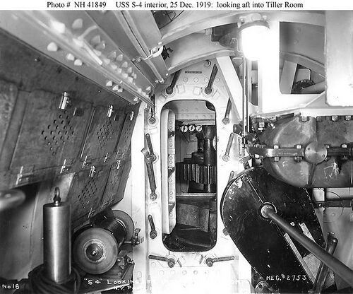
When the S-5 sank in 1920 due to a diving accident, the crew was able to blow the after ballast tanks and raise the stern of the boat above the waves. Only the last 17 feet or so of the stern was above water. The crew took turns entering the tiny tiller room to drill a series of holes in the outer hull using a barely operable and grounded electric drill. They then used a hand saw to connect the holes and cut away a portion of the outer hull just big enough to squeeze a man through. The crew was rescued by passing steamers. Given the size of this small compartment and the fact that the crew had to stand on the bulkhead due to the extreme angle of the boat, it is a miracle that the plan worked.
U.S. Navy photo.
Page created by:
Ric Hedman & David Johnston
1999 - 2023 - PigBoats.COM©
Mountlake Terrace, WA, Norfolk, VA
webmaster at pigboats dot com
