Dolphin 1933 Portsmouth exterior photos
Notes
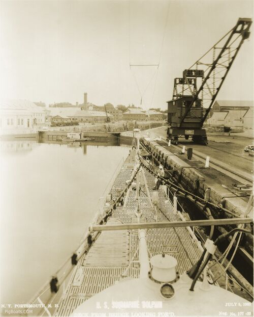
The heavy dual cables on either side of the photo were a combination of medium range radio aerial and mine clearance cable. The lower cable was the aerial and it can be seen connecting to a pressure-proof fitting right at the forward edge of the bridge fairwater.
This heavy cable was supported on the forward and after decks by tri-pod masts and in the center by rectangular stanchions on either side of the bridge fairwater. At the very top of the picture can be seen the much thinner long-range aerial which is supported in the center by the extendable radio mast.
In the lower center of the photo is a mushroom-shaped ventilation valve. It closed off a ventilation intake that serviced the forward half of the boat.
Seen in the lower left of the photo is the under deck storage for one of the ship's launches. To launch the boat the deck covering would be removed, and the boat hoisted out and placed in the water by the torpedo loading derrick. On deck a dungaree-clad Chief Petty Officer can be seen talking with another person, probably a civilian yard worker. Though Chiefs had dress uniforms they had no working uniforms (Khaki) at this time and just wore dungarees the same as lower rates, just adding their round top combination hat.
U.S. Navy photo contributed by Roger Torgeson
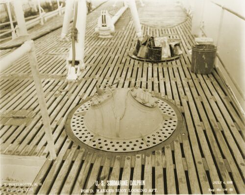
Seen at the top of the photo and just to the right of the tri-pod leg you can see the outline for the under-deck boat storage.
U.S. Navy photo contributed by Roger Torgeson
U.S. Navy photo contributed by Roger Torgeson
U.S. Navy photo contributed by Roger Torgeson
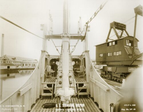
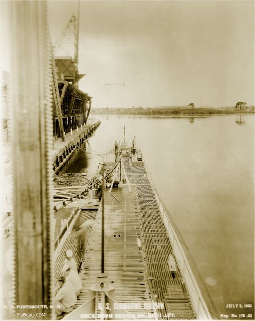
Directly underneath the photographer's feet would be the large, man-sized mushroom shaped main air induction valve, used to draw air into the engine rooms for the diesel engines.
The telescoping radio aerial mast can be seen in the foreground, and in the background is the covered weather bridge. On either side of the periscopes are two fold-up stands used by the lookouts.
The hatch in the deck seen on the left leads up from a void space aft of the conning tower. That space is just outside the deck access door located at the aft end of the conning tower (see interior conning tower photos).
U.S. Navy photo contributed by Roger Torgeson

This is a free flooding area and many of the items located here were made of brass. In the center is the large helm wheel, connected mechanically to a similar unit in the conning tower and control room below.
Next to the wheel is the ship's magnetic compass binnacle, with two arms on each side supporting compensating spheres that zeroed out the effect on the compass of the steel hull. in front of the binnacle is a ventilation pipe.
On the far left and far right are the engine order telegraphs that were used to transmit speed orders for each shaft to the maneuvering room back aft. To the left of the binnacle are rudder angle indicators.
On the right of the binnacle is a curved pipe with a valve. This is the speaking tube down to the conning tower used to send voice commands to the personnel stationed below. The cone sitting on the deck attaches to the valve and concentrates the voice similar to a megaphone. Above the binnacle is a handle that when pulled down actuated the ship's air whistle. The whistle can also be actuated by the two levers attached to the aft end of the enclosure at the top.
The large, heavy tub on the top of the enclosure houses a compass with a pelorus, a rotating ring with folding "peep sights" allowing the user to take bearings of objects used in targeting and or navigation, relative to the submarine. It is watertight and pressure proof and is opened by turning the handle on the right.
U.S. Navy photo contributed by Roger Torgeson
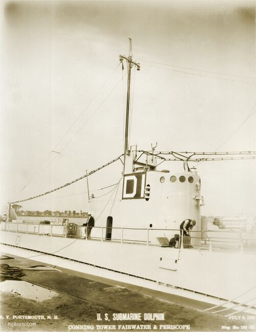
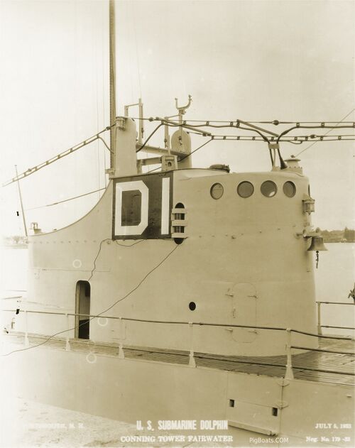
On the forward end of the fairwater can be seen the ship's bell, and two horns for the air whistle. The thick medium range radio aerial wire can be clearly seen here, and the thinner long range aerial is seen supported by the extended mast.
The "D1" on the fairwater is called a class identifier and is used to provide long range visual ID of the boat while it is surfaced, D1 meaning the first boat of the D-Class (as it turned out there was only one boat in this class). Once large numbers of fleet boats began entering surface the use of class identifiers became unwieldy and they were replaced with the boat's hull number in the fall of 1938.
The vertical opening just forward of the D1 is the boat's starboard running light. Directly above the "1" can be seen the upper end of one of the boat's periscopes, and above that is a fork shaped bracket for a search/signal light.
Just forward of the civilian in the sport coat and white hat is a doorless oval opening leading into the interior of the fairwater. This allows crewmen access to the main deck after exiting the conning tower through a watertight door in its aft end.
There are two doored accesses in the fairwater forward (near the two workers), one on the port side and one on the starboard, with the port door being open. The two workers are readying the newly installed accommodation ladder for opening (see photos below).
Note telephone cable running from bridge to the dock to allow submarine to shore communications while in port. The shore phone usually sat in the control room or in the conning tower.
U.S. Navy photo contributed by Roger Torgeson
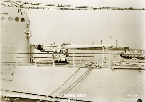
Its bore was made watertight by a removable tampion in the muzzle end and a Smith-Asbury type side swing breech. Even with being watertight the weapon required constant and detailed maintenance or the repeated dunkings in salt water would quickly render it unusable due to corrosion.
U.S. Navy photo contributed by Roger Torgeson
U.S. Navy photo contributed by Roger Torgeson
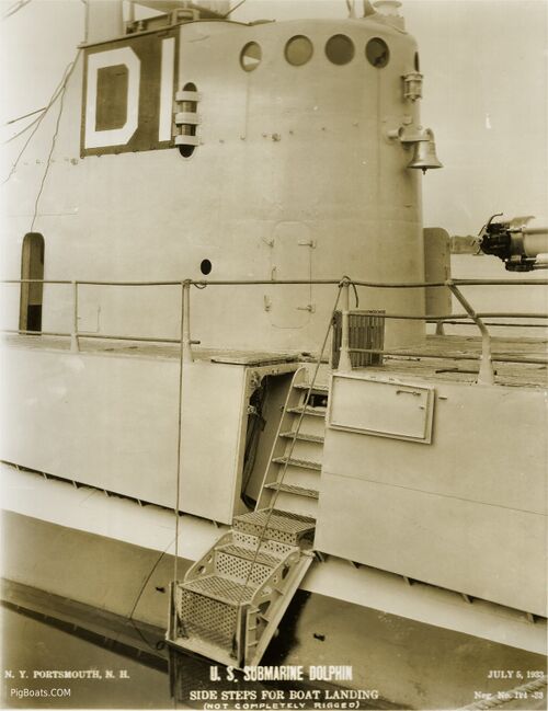
This close up view of the opened accommodation ladder, allowing easy access to the main deck from a small boat alongside. In the 1930's submarines frequently anchored out while in port, or moored to an anchored tender, necessitating the use of the ship's liberty launches to ferry the crew ashore. Just to the left of the ladder the curved hull of the conning tower can barely be seen, inside the superstructure.
U.S. Navy photo contributed by Roger Torgeson
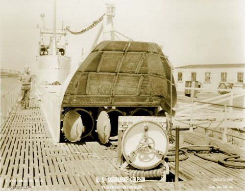
Since the internal torpedo capacity was reduced from 21 to 18 these tubes augmented what was carried below in the two torpedo rooms. The weapons would be pulled out of these tubes and moved below via circular deck hatches in each torpedo rooms. The deck alongside the fairwater was wide enough to allow the torpedoes to be moved forward if necessary. This must have been a harrowing experience in any kind of seaway moving a one-ton torpedo around the moving decks. Most likely they used some sort of wheeled cart that was stored below deck.
The open hatch is located at the forward end of the Engine Room. The Generator Room was directly below the raised deck area.
U.S. Navy photo contributed by Roger Torgeson
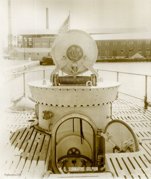
If the rescue chamber was not available or could not be used the crew would make an escape using Momsen Lungs. In this case the top hatch would remain shut and after entering the trunk and shutting the lower hatch the crewmen would flood the trunk to the level of the top of the side door.
This left a small air bubble at the top of the trunk. They would then open the side door, push themselves out, and float to the surface using the Momsen Lung to breathe on the way up. Crewmen inside the boat would then shut the door via a hydraulically operated arm, drain the trunk, then set it up for another use.
The circular hatch in the back of the trunk is the torpedo loading hatch. With this hatch and the side door open torpedoes were carefully winched down on an angle into the after torpedo room. There is a similar trunk on the forward deck leading into the forward torpedo room, but this trunk is less apparent visually because the depth of the superstructure forward allows the top hatch to be flush with the walking deck.
U.S. Navy photo contributed by Roger Torgeson
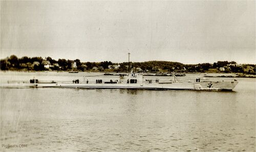
U.S. Navy photo contributed by Roger Torgeson
Page created by:
Ric Hedman & David Johnston
1999 - 2023 - PigBoats.COM©
Mountlake Terrace, WA, Norfolk, VA
webmaster at pigboats dot com
