Torpedo photos & information: Difference between revisions
Pbcjohnston (talk | contribs) |
Pbcjohnston (talk | contribs) |
||
| Line 32: | Line 32: | ||
[[File:D-3 loading torp closeup.jpg|left|500px]] | [[File:D-3 loading torp closeup.jpg|left|500px]] | ||
D-3 hoisting aboard a Mk 4 torpedo that it as just recovered from a practice shot, circa 1912. This photo gives a good view of the aft end of the weapon, including the control surfaces and the twin contra-rotating propellers. The twin propellers spinning in opposite directions eliminated roll torque, preventing the weapon from cork-screwing along its longitudinal axis. Eliminating the roll torque also allowed the gyro to maintain a more accurate course. Note the two very small rudders mounted in cutouts in the upper and lower skeg. The depth control planes were larger but mounted in a similar fashion. The rudder and planes skegs continue aft and form an + shaped guard around the propellers that is attached to the very aft end of the weapon. This was done out of concern that the torpedo's aft end may strike the edge of the tube while exiting and damage the control surfaces and the props. | D-3 hoisting aboard a Mk 4 torpedo that it as just recovered from a practice shot, circa 1912. This photo gives a good view of the aft end of the weapon, including the control surfaces and the twin contra-rotating propellers. The twin propellers spinning in opposite directions eliminated roll torque, preventing the weapon from cork-screwing along its longitudinal axis. Eliminating the roll torque also allowed the gyro to maintain a more accurate course. Note the two very small rudders mounted in cutouts in the upper and lower skeg. The depth control planes were larger but mounted in a similar fashion. The rudder and planes skegs continue aft and form an '''+''' shaped guard around the propellers that is attached to the very aft end of the weapon. This was done out of concern that the torpedo's aft end may strike the edge of the tube while exiting and damage the control surfaces and the props. | ||
[[File:Red bar sub.jpg]] | [[File:Red bar sub.jpg]] | ||
Revision as of 23:45, 21 August 2024

Whitehead Mk 2 & Mk 3

Whitehead Mk 3 torpedoes stored at the weapons depot at Naval Station Cavite, Philippines, approximately 1906. The wheeled carts allowed the quick movement of the weapons from storage to the pier.
Photo in the private collection of Ric Hedman.
![]()
-
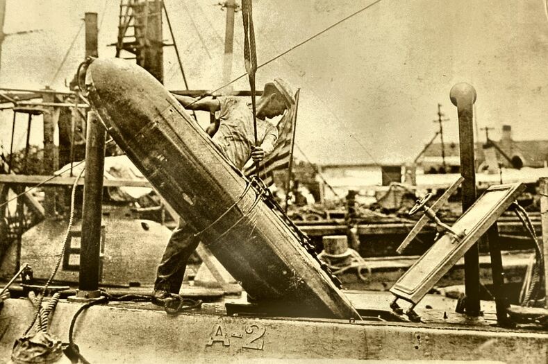 Photo NH 90188 courtesy of the NHHC.
 -
 U.S. Navy photo.


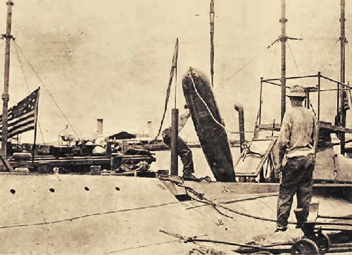
Navy photos of a Mk 3 weapon being loaded into the USS A-2 (Submarine No. 3) at Naval Station Cavite, Philippines, circa 1912. The sailor manhandling the weapon down the hatch gives a good sense of scale to the torpedo, and illustrates how short the mid-body was compared to later torpedoes. Our early submarines were restricted to the use of these short weapons because they were the only ones that would fit inside the boats and the tubes they used. That would quickly change.
![]()
Bliss-Leavitt Mk 4 Mod 1

D-3 hoisting aboard a Mk 4 torpedo that it as just recovered from a practice shot, circa 1912. This photo gives a good view of the aft end of the weapon, including the control surfaces and the twin contra-rotating propellers. The twin propellers spinning in opposite directions eliminated roll torque, preventing the weapon from cork-screwing along its longitudinal axis. Eliminating the roll torque also allowed the gyro to maintain a more accurate course. Note the two very small rudders mounted in cutouts in the upper and lower skeg. The depth control planes were larger but mounted in a similar fashion. The rudder and planes skegs continue aft and form an + shaped guard around the propellers that is attached to the very aft end of the weapon. This was done out of concern that the torpedo's aft end may strike the edge of the tube while exiting and damage the control surfaces and the props.
![]()

Another view of the operation shown above. There is a snubbing line attached to the aft end of the weapon, looped around the #1 periscope. This line allowed the weapon to be gently and carefully lowered into the torpedo room.
![]()
Bliss-Leavitt Mk 6
Currently, PigBoats.COM does not have a good picture of a Mk 6. An idea for its appearance can be gained from the Mk 7 pictures below.
![]()
Bliss-Leavitt Mk 7
In 1922 the Navy undertook a purge of older torpedoes in an effort to simplify the supply chain and ease training issues. All torpedoes prior to the Mk 7 were recalled and removed from service. As we moved towards WWII the Mk 7 was showing its age, but it was retained so that the Navy could equip the old O-class boats that were being brought out of reserve to train new submarine crews. It was the last 18" torpedo used by the Navy.
Bliss produced four additional versions of the Mk 7 for use as aircraft dropped torpedoes. These were pulled out of service when the new Mk 13 was introduced in 1938.

A Mk 7 torpedo on a cart at NTS Newport, August 1913. Overall, it was virtually identical to the Mk 6 in appearance, but it was equipped the the more powerful wet-heater engine. Note the control surfaces forward of the twin contra-rotating propellers. It was a good weapon, but was considered to have an underpowered warhead at only 205 lbs of TNT.
Photo courtesy of the NHHC.
![]()

Mk 7's being loaded onto the L-2 (Submarine No. 41) and L-4 (Submarine No. 43) while in drydock in Bantry Bay Ireland, 1918. The weapon in on the skid and a snubbing line is noosed around the tail. The snubbing line is wrapped around #1 periscope, using the scope as a block to assist lowering the weapon into the torpedo room. The crewman in the peacoat and watch cap right at the aft end of the torpedo is standing on the retracted 3"/23 caliber Mk 9 deck gun.
Photo courtesy of NARA and Navsource.
![]()

K-5 (Submarine No. 36) with a retrieved Mk 7 exercise shot on deck, early 1920's. The explosive warhead has been removed and a water filled inert warhead has replaced it. Torpedoes were very expensive, so there was a great deal of emphasis on retrieving them and reusing them after a peacetime training exercise. At the end of the run, the remaining air in the weapon's air flask would be used to blow the water out of the practice warhead, allowing the weapon to float so that it could be retrieved by the boat that fired it. It only took a half-hour or so to replace the practice head with the real thing if needed.
Photo in the private collection of Ric Hedman.
![]()
Bliss-Leavitt Mk 9 Mod 1B
Shortly after its introduction, the Navy made the tactical decision to discontinue torpedo use on battleships, moving that mission to cruisers and destroyers. The short Mk 9 was ideally suited for submarine use and thus it was modified (Mod 1B) for that new platform. The submarines of the R-class and S-class were in part designed around these weapons and the follow-on Mk 10.
The numbers built were relatively low, as it was supplanted by the Mk 10 with its bigger warhead. The Mk 9 proved to be the swan-song of the E.W. Bliss Company. When production ceased on it in 1920 the Navy awarded no further contracts to Bliss, preferring to consolidate all torpedo production at NTS Newport. The Mk 9, however, was a good weapon and it stayed in the Navy's inventory as a means to supplement the Mk 10. Mk 9's were known to be in the Philippines at the start of World War II in 1941, and some made it to the resupply inventory at Dutch Harbor in the Aleutians, and they were used in combat by the S-boats in those theaters. As far as can be determined, the Mk 9 Mod 1B stayed in Navy use until the end of the war to equip R and S-class submarines stateside, but it is doubtful that they were used in combat much past mid 1942. Once production numbers caught up the Mk 10 was preferred due to its much more powerful warhead.

A Mk 9 Mod 1B torpedo being swung over to the USS S-34 (SS-139) at Naval Operating Base Dutch Harbor, AK, May 14, 1942. The blunt nose of this weapon is apparent here. Another reload is waiting on a cart to the left. A poorly managed industrial base stateside lead to torpedo shortages early in the war and thus the Mk 9's were thrown into action to supplement the Mk 10's until production caught up.
NARA Photo # 80-G-14096 via Navsource.
![]()

Another view of the scene above. Two lines of bolts run the circumference of the weapon, dividing it into three sections. On the left is the warhead and exploder, the middle contains the high pressure air flask and alcohol tank, and on the right is the engine, control surfaces, and propellers. For practice firings, the warhead could be replaced with an exercise head that contained an inert calcium chlorite mixture that simulated the weight of the warhead. Changing the nose was relatively easy and would take less than an hour.
NARA Photo # 80-G-14098 via Navsource.
![]()

A Mk 9 torpedo being gingerly lowered into the torpedo room of S-34 while at Dutch Harbor, AK, May 14, 1942. The weapon is being lowered down the inclined loading skid through the loading hatch. A snubbing line attached to the aft end controls the rate of descent. This photo gives a good view of the aft end of the torpedo, with the rudder and depth control planes visible, along with the twin contra-rotating propellers. The vertical rudders are actually quite small, as they were used only once to turn the weapon onto its preprogrammed course. After that point the weapon ran straight to the impact point. The depth control planes were constantly in use, because the hydrodynamic pressure sensor that sensed the depth was less precise than the gyro that controlled course.
NARA Photo # 80-G-14097 via Navsource.
![]()
Bliss-Leavitt/BuOrd Mk 10 Mod 3
![]()
BuOrd Mk 14
![]()
Westinghouse Mk 18 Mod 1
![]()
BuOrd Mk 23
![]()
Page created by:
Ric Hedman & David Johnston
1999 - 2023 - PigBoats.COM©
Mountlake Terrace, WA, Norfolk, VA
webmaster@pigboats.com
![]()