D-1: Difference between revisions
Pbcjohnston (talk | contribs) →Interior Photos: Added Captions |
Pbcjohnston (talk | contribs) Added captions |
||
| Line 153: | Line 153: | ||
[[File:D-1 haul out 1.jpg|left|500px]] | [[File:D-1 haul out 1.jpg|left|500px]] | ||
<div style="text-align: justify;"><span style="color:#00008B">Narwhal is seen here hauled out on a marine railway, location unknown. The boat looks very new so this may have been a post-builder's trials haul out to fix issues found on the trials. This would place the date sometime in the summer or fall of 1909, but it could be anytime before 1911. The bow cap for the torpedo tubes is very apparent in this photo, especially compared to the construction photos above. At the bottom of the hull just behind the bow cap there is an access plate that has been removed. This would lead into the forward trim tank. There was likely some sort of repair that needed to be done inside the tank. There is also an air or water hose connected to a fitting just aft of the access hole. | |||
<small>Photo courtesy of the Boston Public Library Print Department.</small> | |||
[[File:Red bar sub new.jpg]] | |||
[[File:D-1 stbd.jpg|left|500px]] | [[File:D-1 stbd.jpg|left|500px]] | ||
[[File:D-1 port bow.jpg|left|500px]] | [[File:D-1 port bow.jpg|left|500px]] | ||
Revision as of 20:14, 26 October 2023
Under Construction
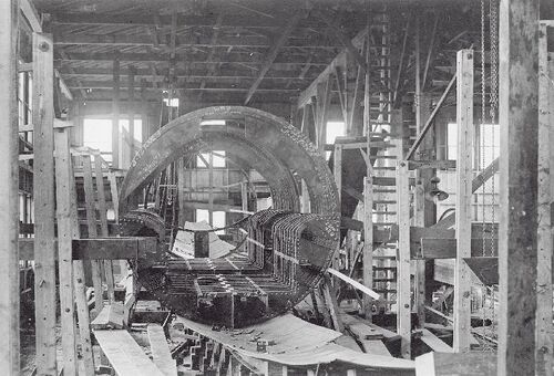
Photo courtesy of the Submarine Force Library & Museum.
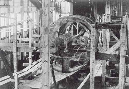
Another photo taken later on the same day shows progress in building the Narwhal. This view is looking from forward to aft. Just beyond the U-shaped ballast tank structure workers have installed the lower framework that will become the foundations for the engines. In the foreground can be seen the curved frame that will form the gasoline tanks under the torpedo room.
Photo courtesy of the Submarine Force Library & Museum.
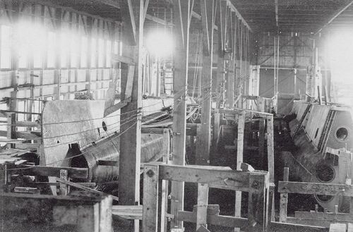
This photo of Narwhal construction was taken 10 months later, on February 7, 1909. Rapid progress has been made. The pressure hull is complete and most of the superstructure has been installed. Narwhal is on the left, Grayling is on the right, in a lesser state of completion. On Narwhal, the superstructure curves around the bow to form the stem, but there is a gap between the stem and the beginning of the pressure hull around the torpedo tubes. The rotating bow cap will be installed there.
Photo courtesy of the Submarine Force Library & Museum.
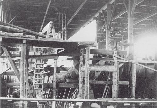
A different view of the same scene above, still with a view of the incomplete bow of Narwhal, February 7, 1909.
Photo courtesy of the Submarine Force Library & Museum.
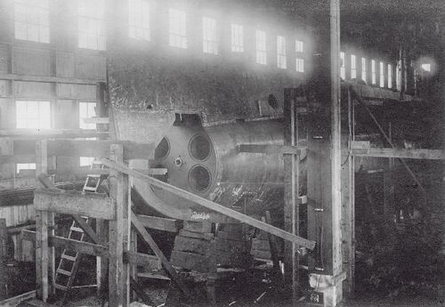
Another angle of the bow area of Narwhal under construction, February 7, 1909. This gives a very clear view of the muzzle end of the torpedo tubes. The streamlined rotating bow cap will be installed later. The cap has two holes in it that will line up with two of the tubes diagonally so that those two tubes can be fired. The cap is then rotated to open up the other two tubes. After firing, the cap is rotated so that the two holes are aligned vertically, and the cap is pulled back and seated firmly so that it seals the muzzle ends of the tubes. The tubes can then be drained and the breech doors inside the torpedo room opened when the boat returns to port. The D-class only carried four torpedoes and no reloads.
Photo courtesy of the Submarine Force Library & Museum.
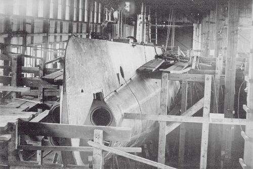
This view of Narwhal's bow while under construction on February 7, 1909 also shows that the conning tower fairwater has been built atop the superstructure in the middle of the boat.
Photo courtesy of the Submarine Force Library & Museum.
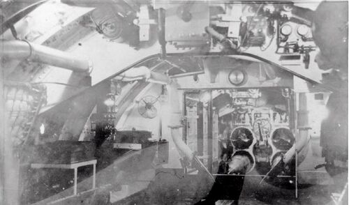
An interior view of Narwhal while under construction at the Fore River Shipbuilding yard in Quincy, MA. This photo was taken on June 12, 1909. The view is from the forward battery area looking forward toward the torpedo room. A large square portion of the torpedo room bulkhead has not yet been installed. See pictures below for what it will look like when complete. The breech doors of the torpedo tubes are open. Yard workers have loaded torpedo "shapes" (inert, non-functioning torpedo simulators) into the tubes to check fit and finish. The two large angled pipes leading upward from the deck right at the bulkhead are battery ventilation pipes that vent hydrogen and heat from the battery while it is being charged. The boat is nearing completion at this point. She would be commissioned five months after this photo was taken.
Photo courtesy of the Submarine Force Library & Museum.
Interior Photos
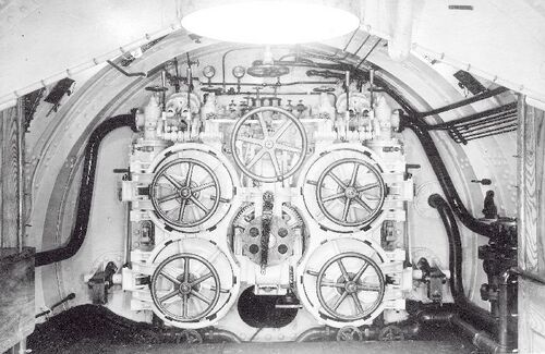
Photo courtesy of the Submarine Force Library & Museum.
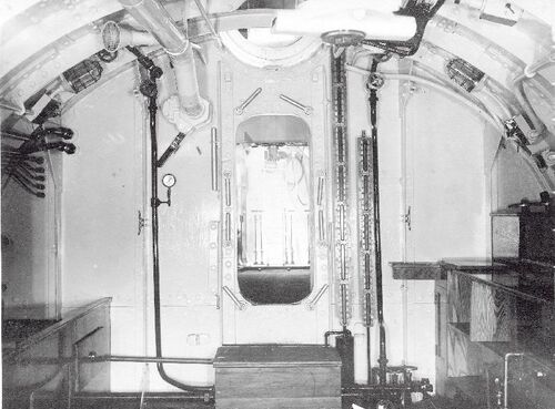
This is Narwhal's torpedo room looking aft. Compared to the photo above, the photographer essentially just turned around. You can see here that the bulkhead that was missing in the construction photo above has now been put into place, with the standard watertight door in the middle. Directly above the door is the circular opening of the angled torpedo loading hatch.
Photo courtesy of the Submarine Force Library & Museum.
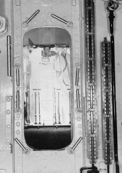
This is a closeup of the photo above, showing the view through the torpedo room watertight door, looking aft into the forward battery compartment and the control room. The ladder seen in the background leads up to the conning tower, and the large levers are for the ballast tank Kingston valves. This view plainly shows that there was not a bulkhead to separate the forward battery from the control room. It was one big compartment.
Photo courtesy of the Submarine Force Library & Museum.
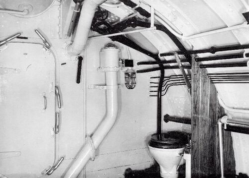
For this photo the photographer stepped through the torpedo room watertight door, turned to the left, then shut the door behind him. This is the forward starboard corner of the forward battery space. On the left is the shut door to the torpedo room, and on the right is the boat's only commode. There is a suspended bar in the overhead that was for a curtain to provide the user of thre commode some level of privacy. The angled pipe against the bulkhead is a battery ventilation line, and it can be seen in the construction photo above that shows the bulkhead missing.
Photo courtesy of the Submarine Force Library & Museum.
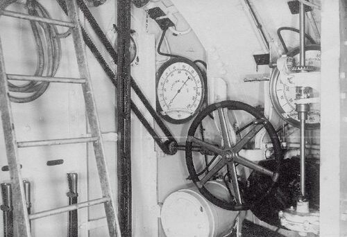
This is the aft end of the Narwhal's combined control room and forward battery space. This view is looking at the aft port corner. The large wheel is the stern planes control station. The chain leads up to rod that leads back to the aft end of the boat to the stern planes themselves. The D-class only had stern planes so there is only one wheel. Two depth gauges are on either side of the wheel. On the left is the ladder leading up to the conning tower. Behind the ladder are the levers for operating the ballast tank Kingston valves.
Photo courtesy of the Submarine Force Library & Museum.
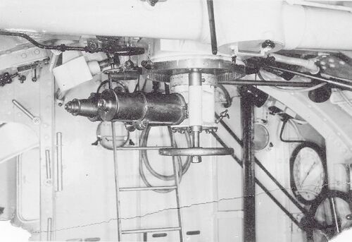
For this photo the photographer has stepped back a few steps so that he could image the periscope eyepiece. This was a non-retractable periscope, but was able to rotate the field of view by turning the large handwheel at the bottom. This instrument was a 4-inch diameter model made by Electric Boat.
On the left of the photo is the open watertight door leading through the bulkhead to the after battery compartment.
Photo courtesy of the Submarine Force Library & Museum.
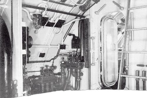
This view is looking aft and to starboard in the control room. On the right is the ladder to the conning tower. In the middle is the door to the after battery compartment. To the left of the door are the high-pressure air and ballast trim mainifolds.
Photo courtesy of the Submarine Force Library & Museum.
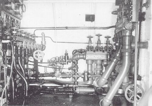
This is a better view of Narwhal's high pressure air and ballast trim manifolds in the starboard aft corner of the control room.
Photo courtesy of the Submarine Force Library & Museum.
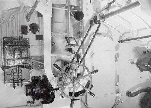
This photo was taken in the after battery compartment looking forward. This is the helm wheel. Very unusually, the designers placed it in the after battery compartment. The placement of the wheel here was dictated by the desire to have a watertight bulkhead separating the control room from the after battery. With the other equipment that was in the control room (stern planes control, ballast control, periscope station, etc.) the helm wouldn't fit so they placed it here. The mirror was used by the helmsman to see the dial of the magnetic compass that was above his head. The handwheel was connected to the steering shaft seen in the upper right by the geared belt and the rudder could be turned completely by hand if necessary, but there was also an electric assist motor in front of the helm (seen here painted black). The horn above the mirror was a voice tube that allowed the helmsman to speak with the Officer of the Deck in the control room or on the bridge.
The second half of the boat's battery would be underneath the helmsman's feet, under the deck.
Photo courtesy of the Submarine Force Library & Museum.
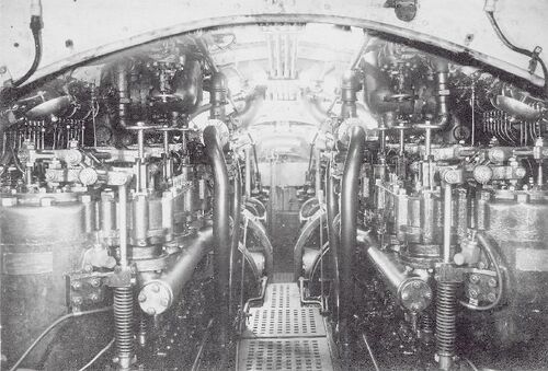
The next compartment aft is the engine room. This compartment is separated from the after battery compartment by a watertight bulkhead. This large compartment contains not only the EB/Craig gasoline engines, but also the clutches, the dynamo generator/motors, and the air compressors. This view is looking aft from the forward end of the compartment.
Photo courtesy of the Submarine Force Library & Museum.
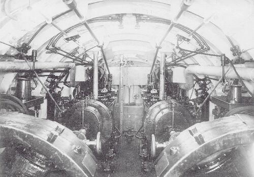
This is a little further aft in the engine room, showing the clutches in the foreground, and the motor/generators further aft.
Photo courtesy of the Submarine Force Library & Museum.
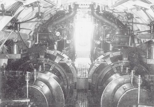
This is from the aft end of Narwhal's engine room looking forward. The motor/generators are in the foreground, then the clutches, and finally the engines. Faintly seen in the far background is the watertight door leading to the after battery compartment. It is somewhat drowned out by light.
Photo courtesy of the Submarine Force Library & Museum.
In Service
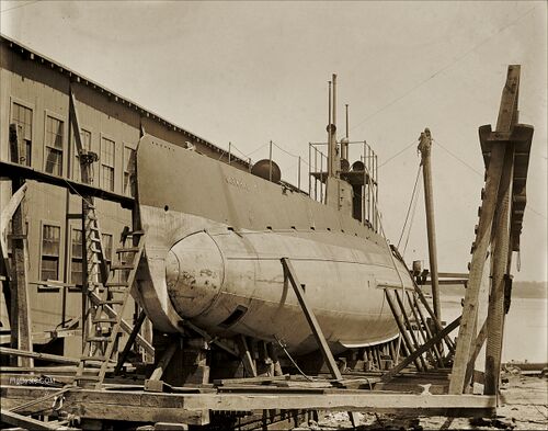
Photo courtesy of the Boston Public Library Print Department.
Page created by:
Ric Hedman & David Johnston
1999 - 2023 - PigBoats.COM©
Mountlake Terrace, WA, Norfolk, VA
webmaster at pigboats dot com
