R-16: Difference between revisions
Pbcjohnston (talk | contribs) |
Pbcjohnston (talk | contribs) Added captions |
||
| Line 223: | Line 223: | ||
[[File:R-16 after battery compartment.jpg|left|500px]] | [[File:R-16 after battery compartment.jpg|left|500px]] | ||
<div style="text-align: justify;"><span style="color:#00008B">Stepping through the door into the after battery compartment and turning back to the door for a peek back into the control room. On the left can be seen the third periscope. To the right is the main electrical switch board. | |||
The periscope is an early Kollmorgen design. It was 18 feet 10½ inches in length and 6 inches in diameter. It had an 8 degree field of view at 6 power. At low power (1.25 power) it gave a 38 degree field of view. | |||
During construction of the R-boats, a desire arose to have a third periscope. Cramming a third scope into the conning tower trunk or into the control room was just not going to work as there wasn't enough room. The existing two scopes were also fairly short and there was a desire to have a longer periscope which gave the advantage of a greater height of eye, and thus a longer visual range. The designers at Electric Boat proposed a scheme to convert an existing access trunk and hatch, used to gain access to the aft deck from the after battery compartment, into a makeshift second conning tower. The hatch at the top would be blanked off and an 18 foot periscope would be added. When fully raised the eyepiece of the scope would be at the top of the trunk, allowing the top of the scope to be considerably higher than the other two. To give the user of the periscope someplace to stand while using it, a platform was attached to the bottom of the scope by a cable, which pulled the platform up with a the scope while it was being raised. Two metal guide rods on each side of the platform kept it straight while raised and provided an additional point to secure the platform. | |||
The designers at the USN Bureau of Construction and Repair agreed with Electric Boat and wanted the third scope installed, but Electric Boat pointed out the because the boats were already under construction making a major change like this would cause a delay in delivery of the boats. Being wartime a delay was not acceptable, so the conversion happened after the boats were delivered to the Navy and commissioned. Ultimately, the third periscope turned out to be not successful, as it tended to vibrate while being used, restricting the boat to a slow speed while it was raised. By the late 1920's the R-boats had standardized on two 27 foot periscopes and presumably the third scope in the after battery was removed and the trunk re-converted to a topside access trunk | |||
<small>Photo in the collection of the Vallejo Naval & Historical Museum. Contributed by Darryl Baker</small> | |||
[[File:Red bar sub new.jpg]] | |||
[[File:R-16 main switches.jpg|left|500px]] | [[File:R-16 main switches.jpg|left|500px]] | ||
<div style="text-align: justify;"><span style="color:#00008B">The main electrical switch board on the starboard side of the compartment. The curved section of the deck below is actually the top of the starboard ballast tanks. | |||
Historian Jim Christley has this to say about this electrical panel set up: "Starting from the top left. On the horizontal bracket. The rectangular item with 66 spots is most probably the Individual Cell Voltage plug board for one of the two batteries. There would be another plug board on the other side of the meter. There were 60 cells per battery so the plug board had some spare plugins as well as one for each end cell terminal. | |||
To the right the two sets of light bulbs were simply an indication of the state of charge of the battery. Brighter meant higher voltage thus higher charge and lower amperage draw. Kind of a quick visual indicator. Between the sets of bulbs are two rectangular boxes with a kind of meter. These most likely are 'amp-hour' meters. They give a numerical reading of the amount of ampere hours charged into and discharged from the battery. If a particular battery had a rating of 4000 amp hours for instance it could output 4000 amps for one hour or 400 amps for 10 hours or 40 amps for 100 hours. Amperes times hours equal amp hours. Thus if the boat is running submerged at the one hour rate of 4000 amps to the motors, the amp hour meter would give an indication of how much battery capacity remained. The other option was to record the specific gravity of the electrolyte which was slower and not as accurate. | |||
Below these are an interesting set of motor operated main power contactors. The old timers when I was first on diesel boats remarked on these. I don't remember exactly what was said but it was not, as I recall, praising their operation. Note that the electrical connections are not enclosed in any way. Not fun in a hot humid or wet situation. Plus finding a place to lean upon with the boat pitching an rolling was an interesting proposition. It was not until the early 1950's that the distribution switch gear became completely enclosed. Above the motor is a set of motor starting flat plate resistors." | |||
<small>Photo in the collection of the Vallejo Naval & Historical Museum. Contributed by Darryl Baker</small> | |||
[[File:Red bar sub new.jpg]] | |||
[[File:R-16 amp hour meters.jpg|left|500px]] | [[File:R-16 amp hour meters.jpg|left|500px]] | ||
<div style="text-align: justify;"><span style="color:#00008B">Amp hour meters for the forward and after batteries. The switches below are covered with a heavy cloth or leather to protect them from condensation or spray. The covering also protected the men from falling into the open switches and being electrocuted. | |||
<small>Photo in the collection of the Vallejo Naval & Historical Museum. Contributed by Darryl Baker</small> | |||
[[File:Red bar sub new.jpg]] | |||
[[File:R-16 after battery compartment2.jpg|left|500px]] | [[File:R-16 after battery compartment2.jpg|left|500px]] | ||
<div style="text-align: justify;"><span style="color:#00008B">This view showing the after port corner of the after battery compartment shows the galley stove and sink area. On the bulkhead is the ships "Watch, Quarter and Station Bill" and also shows the submarine's name, R-16. | |||
<small>Photo in the collection of the Vallejo Naval & Historical Museum. Contributed by Darryl Baker</small> | |||
[[File:Red bar sub new.jpg]] | |||
[[File:R-16 gallery range.jpg|left|500px]] | [[File:R-16 gallery range.jpg|left|500px]] | ||
<div style="text-align: justify;"><span style="color:#00008B">A number of things are sitting on the galley range. What looks like a small coffee pot, a toaster and one more indistinct item. | |||
<small>Photo in the collection of the Vallejo Naval & Historical Museum. Contributed by Darryl Baker</small> | |||
[[File:Red bar sub new.jpg]] | |||
[[File:R-16 wqs bill.jpg|left|500px]] | [[File:R-16 wqs bill.jpg|left|500px]] | ||
<div style="text-align: justify;"><span style="color:#00008B">The WQS bill displays in one place a sailor's duties for each emergency and watch condition. It also shows his administrative and operational duties. A Velvet pipe tobacco can sits on a ledge. | |||
<small>Photo in the collection of the Vallejo Naval & Historical Museum. Contributed by Darryl Baker</small> | |||
[[File:Red bar sub new.jpg]] | [[File:Red bar sub new.jpg]] | ||
<div style="text-align: justify;"><span style="color:#000000"> | |||
=== Engine Room === | === Engine Room === | ||
</div> | |||
[[File:R-16 engine room.jpg|left|500px]] | [[File:R-16 engine room.jpg|left|500px]] | ||
<div style="text-align: justify;"><span style="color:#00008B">We've moved one compartment aft to the engine room. The photo was taken looking aft from the forward end of the compartment. The man at the right is Radio Electricians Mate 3rd Class E. R. Brown. He was seen before in the control room photograph. Seen in the foreground are the engine order telegraphs above the throttle wheels on the front of the diesels. The engines are NELSECO 6-EB-14 diesels built at an Electric Boat subsidiary in Groton, CT. These engines were reasonably reliable and served the boats for their entire lives. | |||
<small>Photo in the collection of the Vallejo Naval & Historical Museum. Contributed by Darryl Baker</small> | |||
[[File:Red bar sub new.jpg]] | |||
[[File:R-16 starboard diesel engine.jpg|left|500px]] | [[File:R-16 starboard diesel engine.jpg|left|500px]] | ||
<div style="text-align: justify;"><span style="color:#00008B">This is a view of the front of the starboard diesel engine showing the instrument cluster, the engine order telegraph and throttle. | |||
<small>Photo in the collection of the Vallejo Naval & Historical Museum. Contributed by Darryl Baker</small> | |||
[[File:Red bar sub new.jpg]] | |||
[[File:R-16 between engines.jpg|left|500px]] | [[File:R-16 between engines.jpg|left|500px]] | ||
<div style="text-align: justify;"><span style="color:#00008B">Another view looking down the engine room between the engines. The door to the motor room can be seen in the background. Just beyond the lower right corner of the door you can see the top of the low pressure ballast pump. The internal framework of these single hull submarines is very evident in the overhead between the engines. | |||
<small>Photo in the collection of the Vallejo Naval & Historical Museum. Contributed by Darryl Baker</small> | |||
[[File:Red bar sub new.jpg]] | |||
[[File:R-16 port diesel engine.jpg|left|500px]] | [[File:R-16 port diesel engine.jpg|left|500px]] | ||
<div style="text-align: justify;"><span style="color:#00008B">This view is looking at the after end of the port diesel engine looking forward. | |||
<small>Photo in the collection of the Vallejo Naval & Historical Museum. Contributed by Darryl Baker</small> | |||
[[File:Red bar sub new.jpg]] | [[File:Red bar sub new.jpg]] | ||
<div style="text-align: justify;"><span style="color:#000000"> | |||
=== Motor Room === | === Motor Room === | ||
</div> | |||
[[File:R-16 motor room.jpg|left|500px]] | [[File:R-16 motor room.jpg|left|500px]] | ||
<div style="text-align: justify;"><span style="color:#00008B">The motor room. The major equipment in this space are the two large main propulsion motors that drive the boat while it is submerged. The deck seems to have been removed, possibly for maintenance work. In the foreground, to the right is the low pressure ballast pump. A ventilation duct runs down the center of the overhead and just aft of the matching curved pipes, on either side of the room are the shaft driven air compressors. The large electric motor just to the left of center is believed to be for the high pressure ballast pump. A few pieces of the equipment seen farther aft could be the lathe and drill press but detail is lacking to make positive determinations. | |||
The room appears to be a bit dirty. Perhaps due to the maintenance work going on. Compared to the appearance of the rest of the submarine this space is pretty messy so this appearance is probably not normal. | |||
<small>Photo in the collection of the Vallejo Naval & Historical Museum. Contributed by Darryl Baker</small> | |||
[[File:Red bar sub new.jpg]] | [[File:Red bar sub new.jpg]] | ||
Revision as of 12:47, 25 September 2023
Exterior and Crew Photos
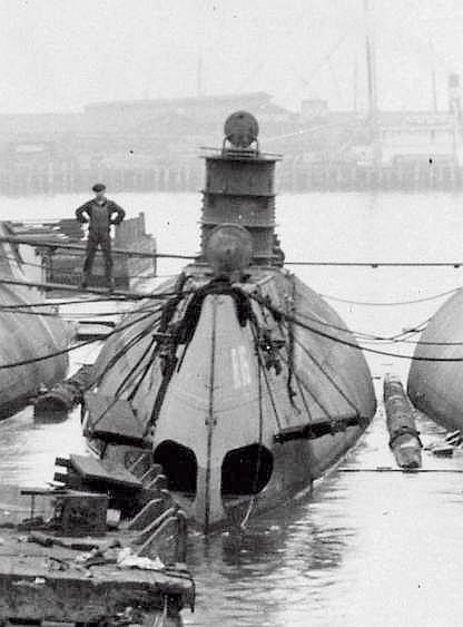
Photo courtesy of the Submarine Force Library & Museum.
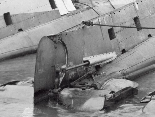
Photo courtesy of the Submarine Force Library & Museum.
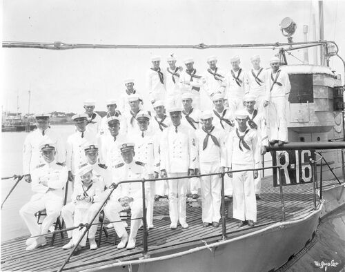
U.S. Navy photo.

Photo courtesy of the USSVWII via Navsource.org
Interior Photos
Notes
Torpedo Room
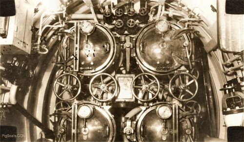
Each door has a sea pressure gauge and sight glass except for door on Number One torpedo tube. The sight glass may have been damaged and has yet to be replaced. The tubes are numbered from right to left and top to bottom; 1, 2 and 3, 4. Odd numbers on the starboard side and even on the port side. The row of large wheel handles are for opening and closing the shutter doors on the outside of the bow. The shutters are inter-linked with the torpedo tube muzzle door that close off the seaward end of the torpedo tube.
The black squares in the corners are from the tabs that glued the photo into the original scrapbook.
Photo in the collection of the Vallejo Naval & Historical Museum. Contributed by Darryl Baker
Forward Battery Compartment/Berthing

The forward battery compartment housed both enlisted crew as well as the sub's three officers. The starboard side, seen here, is for bunks and lockers for enlisted. The port side, blocked off by a canvas curtain is where the officers had their quarters. On the right edge of the photo can be seen the end of a table with cloth over it. This table acted as a desk and eating surface for the officers.
Under the deck was one half of the boat's massive storage battery. It contained 60 cells. The battery well was covered by wood planking and bolted down and then heavy canvas was shellacked down over the planks to make it watertight. Shellac gave the decks their dark green color.
Photo in the collection of the Vallejo Naval & Historical Museum. Contributed by Darryl Baker
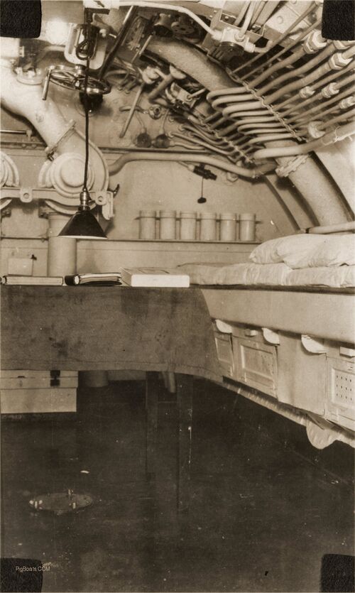
Two of the officer's bunks are seen on the right of the photo. There are storage lockers under the bunks. Not seen are larger cupboards and lockers for officer's use. The purpose of the six canisters against the bulkhead are unknown. They could hold soda lime to absorb CO2 in an emergency, although the containers seem a bit small for that purpose. Battery well ventilation blowers are seen against the bulkhead along with piping to the battery well. This system was used to exhaust battery gases during charging to prevent explosions.
The dark shaft seen to the left of top center, next to the valve handle, is the drive shaft for operating the bow planes.
Photo in the collection of the Vallejo Naval & Historical Museum. Contributed by Darryl Baker
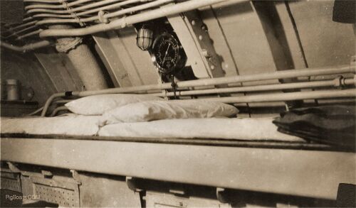
Photo in the collection of the Vallejo Naval & Historical Museum. Contributed by Darryl Baker

Photo in the collection of the Vallejo Naval & Historical Museum. Contributed by Darryl Baker
Control Room

The surrounding gauges seems to be for monitoring the various air pressure systems; 60 psi., 100 psi., 200 psi., & 300 psi. Hinted at but no photo taken, at the left top is another gauge which is possibly part of a series of gauges for the different air banks.
Photo in the collection of the Vallejo Naval & Historical Museum. Contributed by Darryl Baker
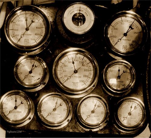
The center row, left to right the dials say: "Aft Trim Tank"; Sea Pressure" and "Fwd Trim Tank".
The bottom row of dials say; "Regulator"; "Auxiliary Tank"; "Aft Main Ballast", and "Fwd Main Ballast".
Photo in the collection of the Vallejo Naval & Historical Museum. Contributed by Darryl Baker
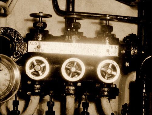
Photo in the collection of the Vallejo Naval & Historical Museum. Contributed by Darryl Baker
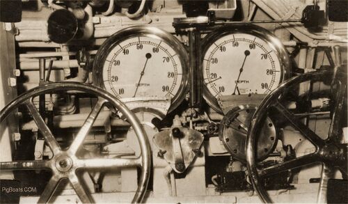
The depth gauges only show 100 feet though the submarines had a test depth of 200 feet. Many skippers complained about having no way of knowing how deep they were after the first 100 feet. Finally the Navy relented and made deeper gauges available.
Above the stern planes wheel is a speaking tube, though where it came from or went isn't known at this time.
Photo in the collection of the Vallejo Naval & Historical Museum. Contributed by Darryl Baker
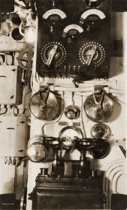
This arrangement sits on the forward side of the bulkhead that enclosed the radio room. The view is looking aft. Between the engine order telegraphs is a bell and on either side of that are small signs that say "PORT" and "STAR". Since the operator is facing aft the controls would be backwards so board is set up as if the operator was facing the other direction. This whole arrangement was moved aft of the engine room in later submarine classes and eventually became what is known as the maneuvering room.
Photo in the collection of the Vallejo Naval & Historical Museum. Contributed by Darryl Baker
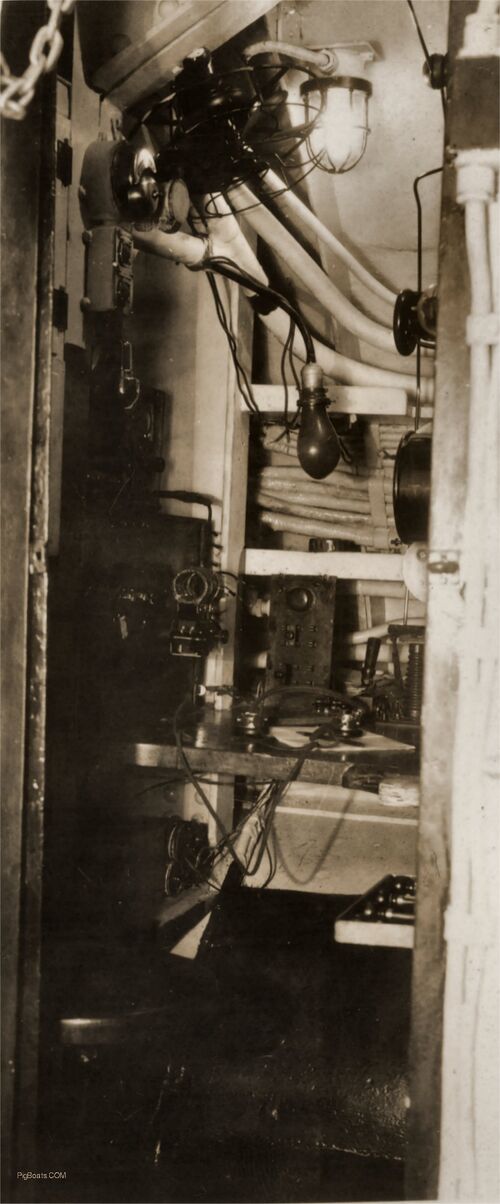
Photo in the collection of the Vallejo Naval & Historical Museum. Contributed by Darryl Baker
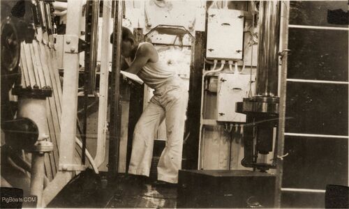
The two large boxes on the bulkhead can also be seen in the photo showing the Motor Controllers. The man standing at a small desk is Radio Electricians Mate 3rd Class E. R. Brown and would have worked in the radio room. He would have also needed to know how to send Morse Code via blinker light and send and read semaphore using hand flags, combining the jobs of Radioman and Signalman into one job on a submarine. The R-16 was stationed at Pearl Harbor for 11 years. These subs had no air conditioning and were hot below decks, hence the reason for the casual dress seen in this photo.
To the left in the photo are seen the levers for operating the Kingston valves that are used for diving or surfacing.
Photo in the collection of the Vallejo Naval & Historical Museum. Contributed by Darryl Baker
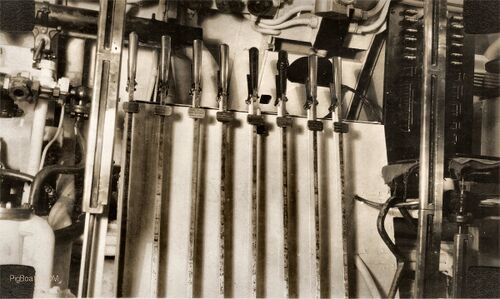
The large sight gauges seen to the right and left of the Kingston levers are, on the right, for the Auxiliary Tanks (there were two of these) and the one on the left is for the Regulator Tank. (This tank is to change its name in the future and become the Negative Tank. All were used to adjust Trim and Weight.)
The large tube in the upper left corner and extending over the top of the first three levers is the barrel cooling tube for the Lewis Mk VI Light Machine Gun that would be mounted on the bridge if needed.
Photo in the collection of the Vallejo Naval & Historical Museum. Contributed by Darryl Baker
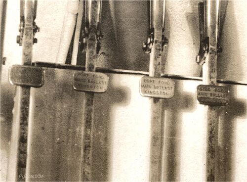
Photo in the collection of the Vallejo Naval & Historical Museum. Contributed by Darryl Baker

The Regulator Tank handle looks to have some sort of coating to make it feel different. The Auxiliary Tank Kingston handle has been wrapped and then a Turks Head Knot applied to it so it feels different from all the rest. It is also painted. This was an attempt to make it easier to operate the levers correctly in the dark.
Photo in the collection of the Vallejo Naval & Historical Museum. Contributed by Darryl Baker
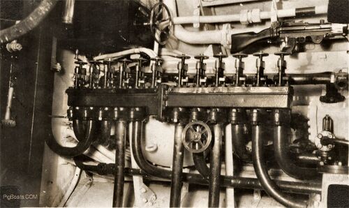
Only a few names can be read on the right side name plate. The far left says "From Bilge". The next two are unreadable. The fourth reads "Trim Line Aft". The fifth reads "From Duct Keel". The last is unreadable. The large back box with the big wheel is the regulator for the trim pump, used for moving the ballast water between the various tanks.
In the upper right corner of the photo the rest of the Lewis Mk VI .30-06 light machine gun can be seen. There were mounts on the bridge where this could be placed if it was needed for protection.
Photo in the collection of the Vallejo Naval & Historical Museum. Contributed by Darryl Baker

Lewis and family settled in England where he became extremely rich from license agreements for his gun. The English and Empire troops used it with much success all through WW I and WW II. After WWI, the U.S. military adopted it in numbers, although it was never as popular as the .30 caliber Browning Machine Gun. There were two calibers for this gun, the British .303 and the American .30-06. The gun used a distinctive 47 or 97 round circular pan magazine mounted on the top of the weapon. It also had extensive cooling fins attached to the barrel, covered by a tube that made the barrel look a lot larger than it really was. Lewis Guns were used by many nations up through the mid 1950's.
If you look closely at the movie "Star Wars: A New Hope" there is a scene in which filmmaker George Lucas adapted a Lewis gun as a Stormtrooper weapon!
Photo in the collection of the Vallejo Naval & Historical Museum. Contributed by Darryl Baker
After Battery Compartment/Crew's Mess

The periscope is an early Kollmorgen design. It was 18 feet 10½ inches in length and 6 inches in diameter. It had an 8 degree field of view at 6 power. At low power (1.25 power) it gave a 38 degree field of view.
During construction of the R-boats, a desire arose to have a third periscope. Cramming a third scope into the conning tower trunk or into the control room was just not going to work as there wasn't enough room. The existing two scopes were also fairly short and there was a desire to have a longer periscope which gave the advantage of a greater height of eye, and thus a longer visual range. The designers at Electric Boat proposed a scheme to convert an existing access trunk and hatch, used to gain access to the aft deck from the after battery compartment, into a makeshift second conning tower. The hatch at the top would be blanked off and an 18 foot periscope would be added. When fully raised the eyepiece of the scope would be at the top of the trunk, allowing the top of the scope to be considerably higher than the other two. To give the user of the periscope someplace to stand while using it, a platform was attached to the bottom of the scope by a cable, which pulled the platform up with a the scope while it was being raised. Two metal guide rods on each side of the platform kept it straight while raised and provided an additional point to secure the platform.
The designers at the USN Bureau of Construction and Repair agreed with Electric Boat and wanted the third scope installed, but Electric Boat pointed out the because the boats were already under construction making a major change like this would cause a delay in delivery of the boats. Being wartime a delay was not acceptable, so the conversion happened after the boats were delivered to the Navy and commissioned. Ultimately, the third periscope turned out to be not successful, as it tended to vibrate while being used, restricting the boat to a slow speed while it was raised. By the late 1920's the R-boats had standardized on two 27 foot periscopes and presumably the third scope in the after battery was removed and the trunk re-converted to a topside access trunk
Photo in the collection of the Vallejo Naval & Historical Museum. Contributed by Darryl Baker

Historian Jim Christley has this to say about this electrical panel set up: "Starting from the top left. On the horizontal bracket. The rectangular item with 66 spots is most probably the Individual Cell Voltage plug board for one of the two batteries. There would be another plug board on the other side of the meter. There were 60 cells per battery so the plug board had some spare plugins as well as one for each end cell terminal.
To the right the two sets of light bulbs were simply an indication of the state of charge of the battery. Brighter meant higher voltage thus higher charge and lower amperage draw. Kind of a quick visual indicator. Between the sets of bulbs are two rectangular boxes with a kind of meter. These most likely are 'amp-hour' meters. They give a numerical reading of the amount of ampere hours charged into and discharged from the battery. If a particular battery had a rating of 4000 amp hours for instance it could output 4000 amps for one hour or 400 amps for 10 hours or 40 amps for 100 hours. Amperes times hours equal amp hours. Thus if the boat is running submerged at the one hour rate of 4000 amps to the motors, the amp hour meter would give an indication of how much battery capacity remained. The other option was to record the specific gravity of the electrolyte which was slower and not as accurate.
Below these are an interesting set of motor operated main power contactors. The old timers when I was first on diesel boats remarked on these. I don't remember exactly what was said but it was not, as I recall, praising their operation. Note that the electrical connections are not enclosed in any way. Not fun in a hot humid or wet situation. Plus finding a place to lean upon with the boat pitching an rolling was an interesting proposition. It was not until the early 1950's that the distribution switch gear became completely enclosed. Above the motor is a set of motor starting flat plate resistors."
Photo in the collection of the Vallejo Naval & Historical Museum. Contributed by Darryl Baker

Photo in the collection of the Vallejo Naval & Historical Museum. Contributed by Darryl Baker
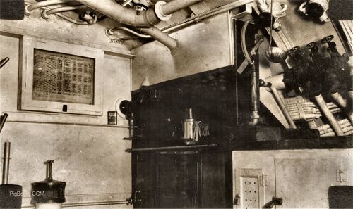
Photo in the collection of the Vallejo Naval & Historical Museum. Contributed by Darryl Baker

Photo in the collection of the Vallejo Naval & Historical Museum. Contributed by Darryl Baker

Photo in the collection of the Vallejo Naval & Historical Museum. Contributed by Darryl Baker
Engine Room
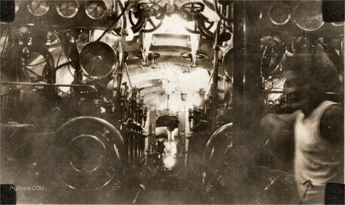
Photo in the collection of the Vallejo Naval & Historical Museum. Contributed by Darryl Baker
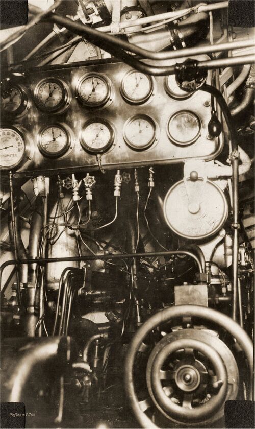
Photo in the collection of the Vallejo Naval & Historical Museum. Contributed by Darryl Baker
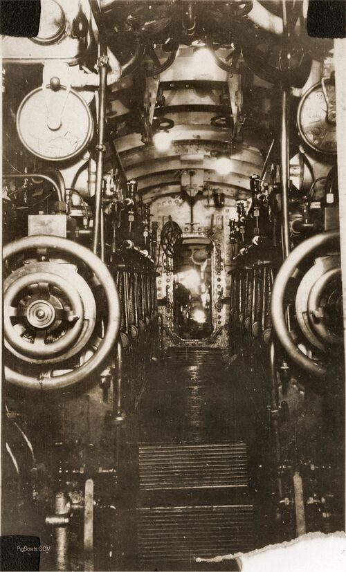
Photo in the collection of the Vallejo Naval & Historical Museum. Contributed by Darryl Baker
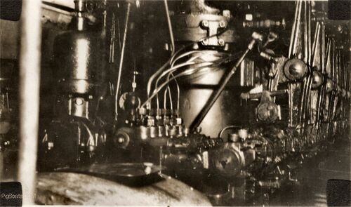
Photo in the collection of the Vallejo Naval & Historical Museum. Contributed by Darryl Baker
Motor Room
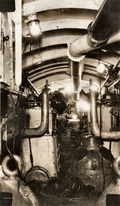
The room appears to be a bit dirty. Perhaps due to the maintenance work going on. Compared to the appearance of the rest of the submarine this space is pretty messy so this appearance is probably not normal.
Photo in the collection of the Vallejo Naval & Historical Museum. Contributed by Darryl Baker
Page created by:
Ric Hedman & David Johnston
1999 - 2023 - PigBoats.COM©
Mountlake Terrace, WA, Norfolk, VA
webmaster at pigboats dot com
