R-16: Difference between revisions
Pbcjohnston (talk | contribs) Added captions |
Pbcjohnston (talk | contribs) Added captions |
||
| Line 104: | Line 104: | ||
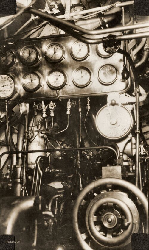
[[File:R-16 control room1.jpg|left|500px]] | [[File:R-16 control room1.jpg|left|500px]] | ||
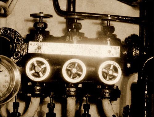
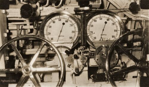
<div style="text-align: justify;"><span style="color:#00008B">This is the forward end of the control room, just to the left of the helm wheel, which is visible on the right. These are valves and gauges for the compressed air system. These gauges give pressures in various banks, tanks, and systems. | |||
The surrounding gauges seems to be for monitoring the various air pressure systems; 60 psi., 100 psi., 200 psi., & 300 psi. Hinted at but no photo taken, at the left top is another gauge which is possibly part of a series of gauges for the different air banks. | |||
<small>Photo in the collection of the Vallejo Naval & Historical Museum. Contributed by Darryl Baker</small> | |||
[[File:Red bar sub new.jpg]] | |||
[[File:R-16 control room2.jpg|left|500px]] | [[File:R-16 control room2.jpg|left|500px]] | ||
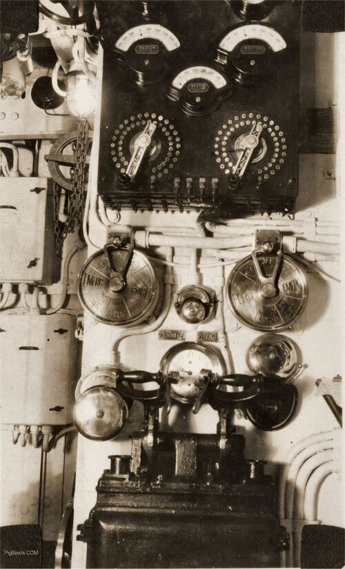
<div style="text-align: justify;"><span style="color:#00008B">In this close up the top row of dials shows, left to right; a gauge marked "Air Flask". The center is a barometer. On the right is a gauge marked "Air Manifold". | |||
The center row, left to right the dials say: "Aft Trim Tank"; Sea Pressure" and "Fwd Trim Tank". | |||
The bottom row of dials say; "Regulator"; "Auxiliary Tank"; "Aft Main Ballast", and "Fwd Main Ballast". | |||
<small>Photo in the collection of the Vallejo Naval & Historical Museum. Contributed by Darryl Baker</small> | |||
[[File:Red bar sub new.jpg]] | |||
[[File:R-16 control room3.jpg|left|500px]] | [[File:R-16 control room3.jpg|left|500px]] | ||
[[File:R-16 control room4.jpg|left|500px]] | [[File:R-16 control room4.jpg|left|500px]] | ||
Revision as of 17:24, 24 September 2023
Exterior and Crew Photos
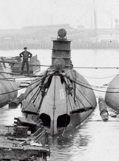
Photo courtesy of the Submarine Force Library & Museum.
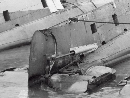
Photo courtesy of the Submarine Force Library & Museum.
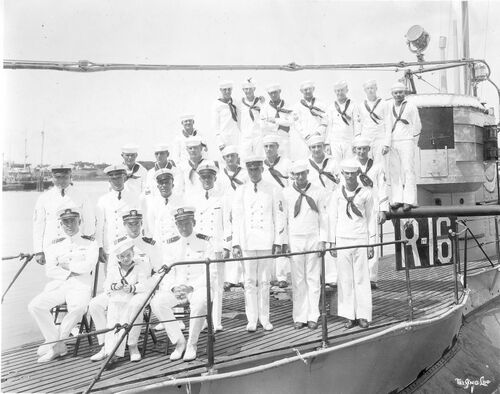
U.S. Navy photo.

Photo courtesy of the USSVWII via Navsource.org
Interior Photos
Notes
Torpedo Room
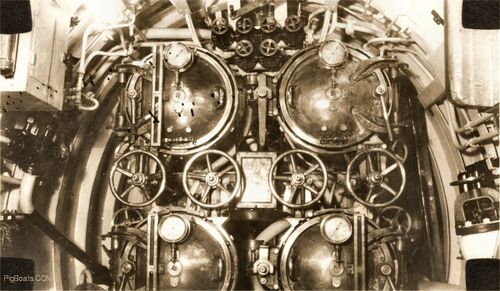
Each door has a sea pressure gauge and sight glass except for door on Number One torpedo tube. The sight glass may have been damaged and has yet to be replaced. The tubes are numbered from right to left and top to bottom; 1, 2 and 3, 4. Odd numbers on the starboard side and even on the port side. The row of large wheel handles are for opening and closing the shutter doors on the outside of the bow. The shutters are inter-linked with the torpedo tube muzzle door that close off the seaward end of the torpedo tube.
The black squares in the corners are from the tabs that glued the photo into the original scrapbook.
Photo in the collection of the Vallejo Naval & Historical Museum. Contributed by Darryl Baker
Forward Battery Compartment/Berthing

The forward battery compartment housed both enlisted crew as well as the sub's three officers. The starboard side, seen here, is for bunks and lockers for enlisted. The port side, blocked off by a canvas curtain is where the officers had their quarters. On the right edge of the photo can be seen the end of a table with cloth over it. This table acted as a desk and eating surface for the officers.
Under the deck was one half of the boat's massive storage battery. It contained 60 cells. The battery well was covered by wood planking and bolted down and then heavy canvas was shellacked down over the planks to make it watertight. Shellac gave the decks their dark green color.
Photo in the collection of the Vallejo Naval & Historical Museum. Contributed by Darryl Baker
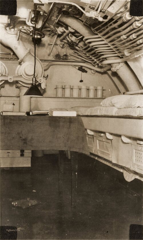
Two of the officer's bunks are seen on the right of the photo. There are storage lockers under the bunks. Not seen are larger cupboards and lockers for officer's use. The purpose of the six canisters against the bulkhead are unknown. They could hold soda lime to absorb CO2 in an emergency, although the containers seem a bit small for that purpose. Battery well ventilation blowers are seen against the bulkhead along with piping to the battery well. This system was used to exhaust battery gases during charging to prevent explosions.
The dark shaft seen to the left of top center, next to the valve handle, is the drive shaft for operating the bow planes.
Photo in the collection of the Vallejo Naval & Historical Museum. Contributed by Darryl Baker
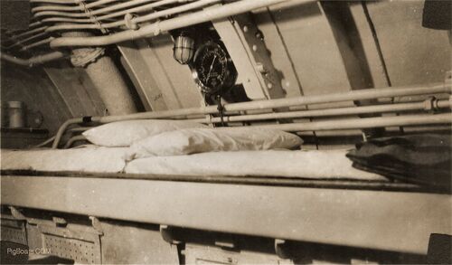
Photo in the collection of the Vallejo Naval & Historical Museum. Contributed by Darryl Baker

Photo in the collection of the Vallejo Naval & Historical Museum. Contributed by Darryl Baker
Control Room

The surrounding gauges seems to be for monitoring the various air pressure systems; 60 psi., 100 psi., 200 psi., & 300 psi. Hinted at but no photo taken, at the left top is another gauge which is possibly part of a series of gauges for the different air banks.
Photo in the collection of the Vallejo Naval & Historical Museum. Contributed by Darryl Baker
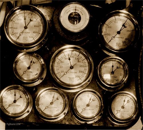
The center row, left to right the dials say: "Aft Trim Tank"; Sea Pressure" and "Fwd Trim Tank".
The bottom row of dials say; "Regulator"; "Auxiliary Tank"; "Aft Main Ballast", and "Fwd Main Ballast".
Photo in the collection of the Vallejo Naval & Historical Museum. Contributed by Darryl Baker


After Battery Compartment/Crew's Mess




Engine Room
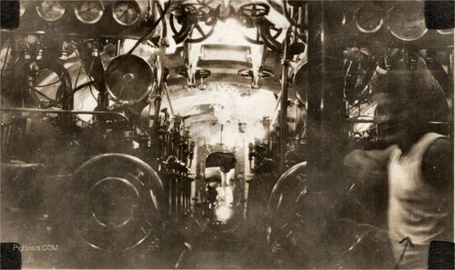
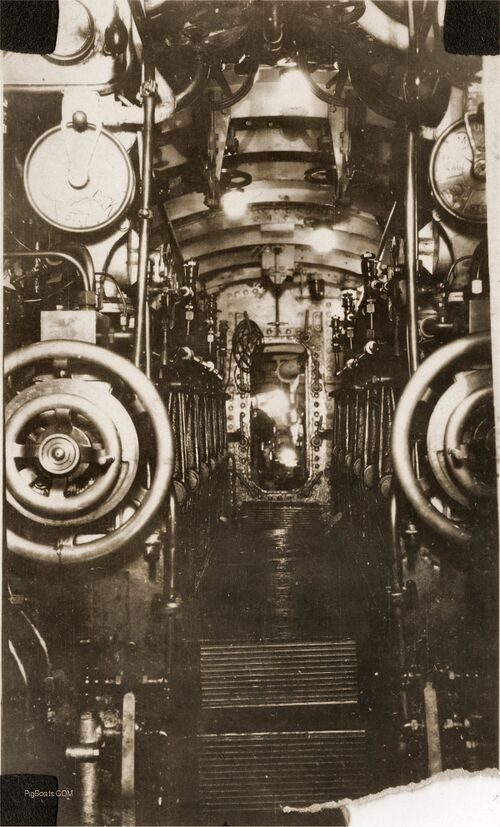
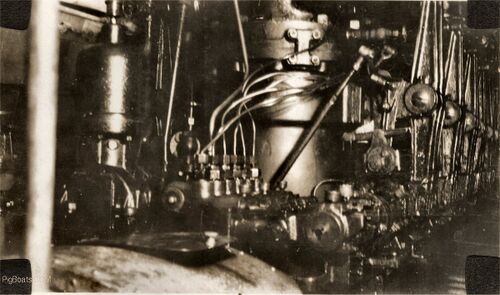
Motor Room
Page created by:
Ric Hedman & David Johnston
1999 - 2023 - PigBoats.COM©
Mountlake Terrace, WA, Norfolk, VA
webmaster at pigboats dot com
