Dolphin 1932 drydocking: Difference between revisions
Pbcjohnston (talk | contribs) Started adding photos |
Pbcjohnston (talk | contribs) No edit summary |
||
| Line 25: | Line 25: | ||
The numbers running vertically above the tubes are draft marks, used to tell the crew how deep in the water the boat is sitting while in port. Each number is 6 inches tall and there are 6 inches from the bottom of one number to the top of the next. The bottom "0" actually corresponds to 10 feet, meaning that when the water line is at the bottom of the 0 the hull directly below this number is 10 feet under the water. The "1" corresponds to 11 feet, and so on. | The numbers running vertically above the tubes are draft marks, used to tell the crew how deep in the water the boat is sitting while in port. Each number is 6 inches tall and there are 6 inches from the bottom of one number to the top of the next. The bottom "0" actually corresponds to 10 feet, meaning that when the water line is at the bottom of the 0 the hull directly below this number is 10 feet under the water. The "1" corresponds to 11 feet, and so on. | ||
<small>US Navy Photo Contributed by Roger Torgeson</small> | |||
[[File:Red bar sub new.jpg]] | |||
[[File:Dolphin-ext-014.jpg|left|500px]] | |||
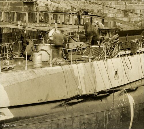
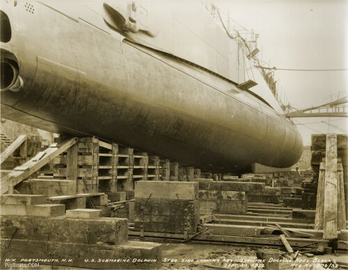
<div style="text-align: justify;"><span style="color:#00008B">View of the outer hull, port side, looking aft. One of the two anchors can be seen, along with the bottom edge of the free flooding superstructure in the middle of the photo. On the bottom of the hull on the right can be seen the port side bilge keel, a slat like device designed to lessen the effects of wave induced rolling while on the surface. | |||
<small>US Navy Photo Contributed by Roger Torgeson</small> | |||
[[File:Red bar sub new.jpg]] | |||
[[File:Dolphin-ext-015.jpg|left|500px]] | |||
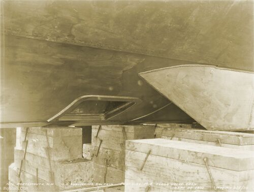
<div style="text-align: justify;"><span style="color:#00008B">The square shaped object is a Kingston valve for a port side ballast tank. These valves allow seawater to flood into the ballast tank, giving the boat the negative buoyancy needed to dive. It is closed in this view. Note the riveted hull plating but the welded bilge keel. A mix of construction styles. | |||
<small>US Navy Photo Contributed by Roger Torgeson</small> | |||
[[File:Red bar sub new.jpg]] | |||
[[File:Dolphin-ext-016.jpg|left|500px]] | |||
<div style="text-align: justify;"><span style="color:#00008B">The same view as the photo above, but with the Kingston valve open. Note the welding bead around the Kingston valve flange and around the edge of the bilge keel, but the riveted hull plating above. | |||
<small>US Navy Photo Contributed by Roger Torgeson</small> | |||
[[File:Red bar sub new.jpg]] | |||
[[File:Dolphin-ext-017.jpg|left|500px]] | |||
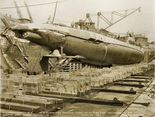
<div style="text-align: justify;"><span style="color:#00008B">View of the boat in drydock at Portsmouth Navy Yard, 30 September 1932. The aft torpedo tubes can clearly be seen, just below and aft of the angle-steel propeller guards. | |||
The stern diving planes are mounted to the rudder stock and are aft of the propellers (properly called a screw). The stern planes are used to control the angle of the boat while submerged. | |||
On the main deck the aft escape trunk can be seen, and just forward of that are two raised platforms that cover the large mufflers for the main propulsion diesel engines. Just below the muffler platform is a circular opening in the side of the superstructure. This is the exhaust pipe leading out from the muffler. Further forward you can just see the exhaust pipe outlet for the starboard side generator diesel. | |||
<small>US Navy Photo Contributed by Roger Torgeson</small> | |||
[[File:Red bar sub new.jpg]] | |||
[[File:Dolphin-ext-018.jpg|left|500px]] | |||
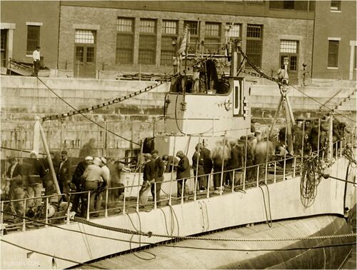
<div style="text-align: justify;"><span style="color:#00008B">Close up of the conning tower fairwater, starboard side looking forward. This is the original configuration of the fairwater, with a stepped configuration that leads down to an enclosure for one of the two liberty launches. | |||
<small>US Navy Photo Contributed by Roger Torgeson</small> | |||
[[File:Red bar sub new.jpg]] | |||
[[File:Dolphin-ext-019.jpg|left|500px]] | |||
<div style="text-align: justify;"><span style="color:#00008B">Close up of the after deck showing details of the escape trunk, muffler platforms, and engine exhaust. Someone spilled a paint bucket! | |||
<small>US Navy Photo Contributed by Roger Torgeson</small> | |||
[[File:Red bar sub new.jpg]] | |||
[[File:Dolphin-ext-020.jpg|left|500px]] | |||
<div style="text-align: justify;"><span style="color:#00008B">Starboard side from aft, down in the drydock showing details of the stern. | |||
<small>US Navy Photo Contributed by Roger Torgeson</small> | <small>US Navy Photo Contributed by Roger Torgeson</small> | ||
Revision as of 16:05, 20 June 2023
US Navy Photo Contributed by Roger Torgeson
US Navy Photo Contributed by Roger Torgeson
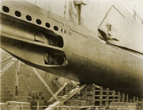
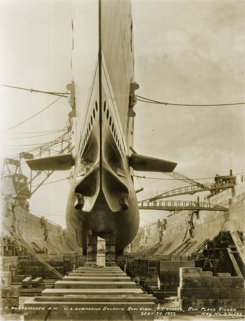
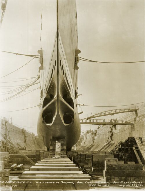
The second piece is a hydrodynamic fairing attached via a hinge to the outer door. When shut this fairing provides a smooth flow of water. When open it partially retracts into the superstructure to get out of the way of the weapon as it exits. The bumper on the fairing prevents the weapon from hanging up on or hitting the superstructure. As you can see there is also a bumper on the inside of the circular outer door for the same purpose.
The mechanism for opening and closing these tube fairings was fairly complicated and would have most likely caused the boat some maintenance problems.
The oval cutouts above the tubes are called limber holes and they allow rapid flooding and/or draining of this portion of the superstructure, which is open to the sea. The pressure hull is buried inside the outer hull to the right of this picture and can not be seen.
The numbers running vertically above the tubes are draft marks, used to tell the crew how deep in the water the boat is sitting while in port. Each number is 6 inches tall and there are 6 inches from the bottom of one number to the top of the next. The bottom "0" actually corresponds to 10 feet, meaning that when the water line is at the bottom of the 0 the hull directly below this number is 10 feet under the water. The "1" corresponds to 11 feet, and so on.
US Navy Photo Contributed by Roger Torgeson
US Navy Photo Contributed by Roger Torgeson

US Navy Photo Contributed by Roger Torgeson
US Navy Photo Contributed by Roger Torgeson
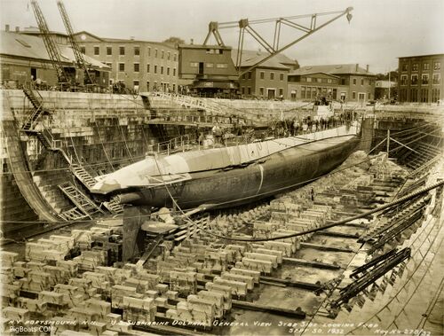
The stern diving planes are mounted to the rudder stock and are aft of the propellers (properly called a screw). The stern planes are used to control the angle of the boat while submerged.
On the main deck the aft escape trunk can be seen, and just forward of that are two raised platforms that cover the large mufflers for the main propulsion diesel engines. Just below the muffler platform is a circular opening in the side of the superstructure. This is the exhaust pipe leading out from the muffler. Further forward you can just see the exhaust pipe outlet for the starboard side generator diesel.
US Navy Photo Contributed by Roger Torgeson
US Navy Photo Contributed by Roger Torgeson
