Dolphin Control and Pump Room: Difference between revisions
Pbcjohnston (talk | contribs) mNo edit summary |
Pbcjohnston (talk | contribs) Added pictures |
||
| Line 81: | Line 81: | ||
[[File:Dolphin Control aft-1f.jpg|left|500px]] | [[File:Dolphin Control aft-1f.jpg|left|500px]] | ||
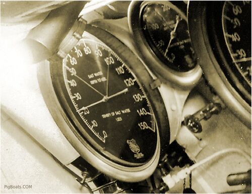
<div style="text-align: justify;"><span style="color:#00008B">A closeup of the depth gauges. The two large ones are shallow water gauges, which go to only 150 feet. The smaller one in the center is the deep water gauge, calibrated to what appears to be 400 feet. Depth is measured to the keel. | <div style="text-align: justify;"><span style="color:#00008B">A closeup of the depth gauges. The two large ones are shallow water gauges, which go to only 150 feet. The smaller one in the center is the deep water gauge, calibrated to what appears to be 400 feet. Depth is measured to the keel. | ||
<small>US Navy Photo Contributed by Roger Torgeson</small> | |||
[[File:Red bar sub new 2.jpg]] | |||
[[File:Dolphin Control fwd stbd-1.jpg|left|500px]] | |||
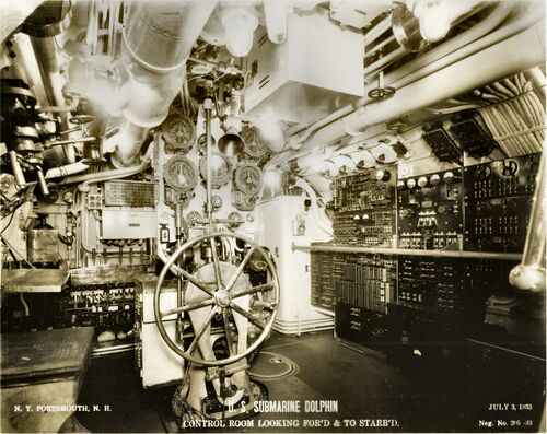
<div style="text-align: justify;"><span style="color:#00008B">Another view of the control room looking forward this time showing some detail in the forward starboard corner of the room. The enclosed cabinet in the far corner is probably an electrical equipment storage space. Spare parts, fuses, tubes, etc. It's purpose is not known for sure at the present time. | |||
<small>US Navy Photo Contributed by Roger Torgeson</small> | |||
[[File:Red bar sub new 2.jpg]] | |||
[[File:Dolphin Control fwd stbd-1b.jpg|left|500px]] | |||
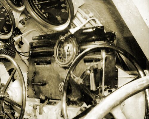
<div style="text-align: justify;"><span style="color:#00008B">A second Christmas Tree appears to be on the left of the photo. Open and Shut indicators are evident but no location names can be read. Notice the engine order telegraphs. The lower set are used by the helmsman to send orders aft, the upper set indicates that Maneuvering has acknowledged the order. A rudder angle indicator is in the center. The vertical rod and lever are for engaging/disengaging the conning tower and bridge helm wheels. A conical voice tube with a shut off valve connects the helmsman to the Officer of the Deck on the bridge and to maneuvering. | |||
<small>US Navy Photo Contributed by Roger Torgeson</small> | |||
[[File:Red bar sub new 2.jpg]] | |||
[[File:Dolphin Control fwd stbd-1c.jpg|left|500px]] | |||
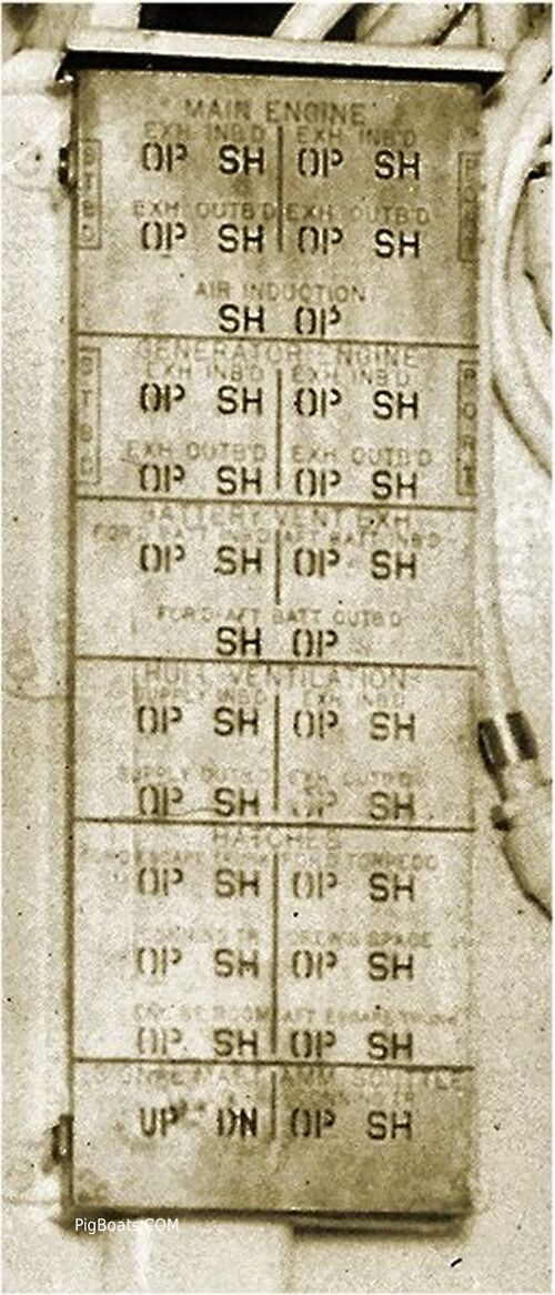
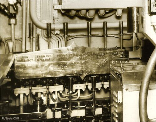
<div style="text-align: justify;"><span style="color:#00008B">Close up of the hydraulic Vent/Flood control panel. This operates the hydraulics for opening the vents and Kingston valves for the submarine's ballast and auxiliary tankage. It seems that only the Main Middle Ballast Tanks (Port and Starboard), and the Safety tank have Kingston valves. The last signage on the right has the word "Ventilation" but we do not know if there was any other description that went with this and why was it on a diving valve manifold? Perhaps this was a valve for inboard ventilation? | |||
<small>US Navy Photo Contributed by Roger Torgeson</small> | |||
[[File:Red bar sub new 2.jpg]] | |||
[[File:Dolphin Control stbd-1.jpg|left|500px]] | |||
<div style="text-align: justify;"><span style="color:#00008B">Control room looking to starboard and aft. In many respects this is the general layout for the starboard side of control rooms throughout the coming sequence of submarines through WW II and after. The type of equipment will change with newer and more modern versions as time passes but this was the template for the future. Electrical panels at the left will become enclosed to prevent short due to condensation and for crew safety as time went on. | |||
Just to the right of these panels is a barometer. This was important to letting the crew know what was happening with weather but also in letting them know the submarine was closed up properly for diving. When all hatches and valves were closed a small amount of air was bled into the submarine and the barometer would register this pressure change. If everything was closed properly the pressure would not change. The report; "Pressure in the boat", would signal all was well and the dive could proceed. An important piece of equipment indeed. | |||
Moving right we see the row of gauges for the air system and air banks and various pressures. The manifold seen below these gauges is the trim manifold which ports internal ballasting water around the boat. Air system valves are to the right and below of this manifold. | |||
The row of large valves and piping seen in the overhead are associated with the Fuel Ballast Tank System. | |||
<small>US Navy Photo Contributed by Roger Torgeson</small> | |||
[[File:Red bar sub new 2.jpg]] | |||
[[File:Dolphin Control stbd-1b.jpg|left|500px]] | |||
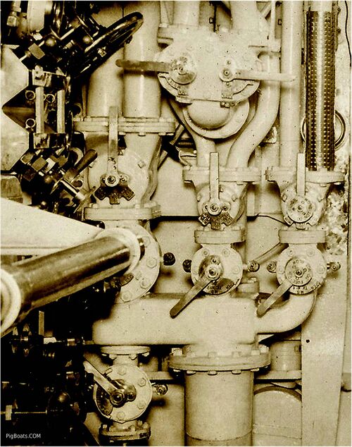
<div style="text-align: justify;"><span style="color:#00008B">Air bank gauges and manifolds with the variable water trim manifold in the center. Tucked in behind at the top of the trim manifold can be seen two "T" handle wrenches for operating this manifold. | |||
Labels on the trim manifold, top row of valves: "Aux Bal, Tk No1 Blow", "Aux Bal, Tk No2 Blow", "For'd Trim Tank Blow", "Aft Trim Tank Blow". | |||
Bottom Row: "Aux Bal, Tk No1 Vent", "Aux Bal, Tk No2 Vent", "For'd Trim Tank Vent", "Aft Trim Tank Vent". | |||
The three valve handles on the left read, Top: "200# Air For'd" and the bottom one reads "200# Air Aft". The center handle has nothing readable except "open" | |||
The bottom large handle says "200# Air From Reducer" Meaning Higher pressure air was sent through a reducer to become 200 pound air. | |||
<small>US Navy Photo Contributed by Roger Torgeson</small> | |||
[[File:Red bar sub new 2.jpg]] | |||
[[File:Dolphin Control stbd-1d.jpg|left|500px]] | |||
<div style="text-align: justify;"><span style="color:#00008B">The heavy casting of this manifold indicates that it is the high pressure air manifold. | |||
<small>US Navy Photo Contributed by Roger Torgeson</small> | <small>US Navy Photo Contributed by Roger Torgeson</small> | ||
Revision as of 19:03, 15 June 2023
Control Room

In the center above the helm wheel is the rudder angle indicator, flanked on both sides by the engine order telegraphs. The lever on the vertical shaft was used to engage/disengage the control room helm from the conning tower and bridge helm. Which helm would have been the primary station for submerged operations? We would lean towards the conning tower, but that opinion might be flavored by what was done in combat in WWII and may not necessarily reflect pre-war 1930's practice.
Large levers next to helm are for switching from normal hydraulic to hand hydraulic. In hand hydraulic you spun the wheel to develop hydraulic pressure and this was a very laborious process.
Oval hatch in deck next to helm most likely leads to a store room. Note speaking tube to conning tower above the helm.
US Navy Photo Contributed by Roger Torgeson

Open grate in the deck leads most likely to the Pump Room and the grating is for drainage of any flooding into the Pump Room, where it can be pumped out through the main drainage system.
The square hatch is suspected to be the access to the Cold Room/Freezer. The padlock seen on the hatch seems to correspond to other food storage areas with padlocks making us think this is that space. Drawings indicate that the Cold Room/Freezer was directly under the middle of the Control Room.
On the right edge of the photo, just below the polished bell of the speaking tube, and above the battle lantern, is the mechanical linkage for the bow planes coming out of the angled enclosure just above and to the right of the bow planes control wheel.
US Navy Photo Contributed by Roger Torgeson

US Navy Photo Contributed by Roger Torgeson

US Navy Photo Contributed by Roger Torgeson
US Navy Photo Contributed by Roger Torgeson

US Navy Photo Contributed by Roger Torgeson
US Navy Photo Contributed by Roger Torgeson
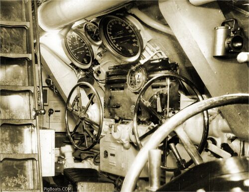
The large, angled sheet metal enclosures, to the left and right of the stern planes and bow planes wheels, cover the mechanical linkages for the stern and bow planes control rods.
US Navy Photo Contributed by Roger Torgeson
US Navy Photo Contributed by Roger Torgeson
US Navy Photo Contributed by Roger Torgeson
US Navy Photo Contributed by Roger Torgeson

US Navy Photo Contributed by Roger Torgeson
US Navy Photo Contributed by Roger Torgeson
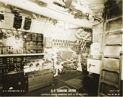
Just to the right of these panels is a barometer. This was important to letting the crew know what was happening with weather but also in letting them know the submarine was closed up properly for diving. When all hatches and valves were closed a small amount of air was bled into the submarine and the barometer would register this pressure change. If everything was closed properly the pressure would not change. The report; "Pressure in the boat", would signal all was well and the dive could proceed. An important piece of equipment indeed.
Moving right we see the row of gauges for the air system and air banks and various pressures. The manifold seen below these gauges is the trim manifold which ports internal ballasting water around the boat. Air system valves are to the right and below of this manifold.
The row of large valves and piping seen in the overhead are associated with the Fuel Ballast Tank System.
US Navy Photo Contributed by Roger Torgeson

Labels on the trim manifold, top row of valves: "Aux Bal, Tk No1 Blow", "Aux Bal, Tk No2 Blow", "For'd Trim Tank Blow", "Aft Trim Tank Blow". Bottom Row: "Aux Bal, Tk No1 Vent", "Aux Bal, Tk No2 Vent", "For'd Trim Tank Vent", "Aft Trim Tank Vent". The three valve handles on the left read, Top: "200# Air For'd" and the bottom one reads "200# Air Aft". The center handle has nothing readable except "open" The bottom large handle says "200# Air From Reducer" Meaning Higher pressure air was sent through a reducer to become 200 pound air.
US Navy Photo Contributed by Roger Torgeson

US Navy Photo Contributed by Roger Torgeson
Page created by:
Ric Hedman & David Johnston
1999 - 2023 - PigBoats.COM©
Mountlake Terrace, WA, Norfolk, VA
webmaster at pigboats dot com
