T-3 interior photos: Difference between revisions
Pbcjohnston (talk | contribs) Added photos |
Pbcjohnston (talk | contribs) Finished T-3 interior page |
||
| Line 222: | Line 222: | ||
[[File:Red bar sub new.jpg]] | [[File:Red bar sub new.jpg]] | ||
[[File:T-3 periscopes.jpg]] | [[File:T-3 periscopes.jpg|left|500px]] | ||
<div style="text-align: justify;"><span style="color:#00008B">Another photo of a T-class control room, likely taken at the same time as the one above. Both pericopes are raised and the diving planes operators can be seen in the background. | |||
<small>U.S. Navy photo</small> | |||
[[File:Red bar sub new.jpg]] | |||
[[File:T-3 control 2.jpg|left|500px]] | |||
<div style="text-align: justify;"><span style="color:#00008B">Control room looking aft and to starboard. On the left, the periscopes and their cables for raising and lowering can be seen again. This time both scopes are raised. The large panel seen to the left is the main electrical distribution board. It is composed of open knife switches. A railing surrounds the panel to keep people from falling into the panel and the switches. | |||
The ladder seen here is in its stored position. The actual access to the bridge is in the forward port side of the compartment in the area of the high pressure air manifold in the previous photo. It can't be seen because of the large main frame between it and the camera. | |||
The door leads into the airlock that opens into the engine room. To the right of the door are large rheostats that are used to regulate electrical power from the batteries as it is fed to the motors. In later submarines this space was moved aft and placed into its own room. | |||
On the very right side is a bench that holds a coffee pot and an old fashioned 'daffodil' style telephone. Below the bench are a number of unused motors and fans. | |||
<small>Photo courtesy of Sean Hert via Mike Mohl and Navsource.org.</small> | |||
[[File:Red bar sub new.jpg]] | |||
<div style="text-align: justify;"><span style="color:#000000"> | |||
=== Engine Room === | |||
</div> | |||
[[File:T-3 engine room 1.jpg|left|500px]] | |||
<div style="text-align: justify;"><span style="color:#00008B">Engine room, looking forward from about the middle of the compartment. Through the doorway you can see into the control room and the helm and barrel of one of the two periscopes. This is another "airlock" door with about 3 feet between the two doors. This is to regulate how the air flows into the engine room. Having these doors shut forces the engines to suck in air via the induction system. If these doors were open there would be a gale of air roaring through the forward compartments. | |||
Above the door are two fuel "gravity tanks". Fuel for the engines was pumped up from the sump tank, through three fuel filters, (the quality of diesel fuel was still pretty iffy and contamination by dirt a possibility for fouling the engine fuel inlets), and into the tanks, where the force of gravity would keep a constant feed to the fuel racks. The tanks feed fuel from a line that sat about 3 to 4 inches off the bottom of the tank to the engines. This was to prevent and dirt of sludge from being picked up by the fuel intakes and delivered to the diesels. | |||
Sight glasses to show the condition of the tanks can be seen on the front of them. The starboard tank show that the tank has been isolated from the port tank and is only about 1/3 full while the port tank is showing to be full. If the tanks were cross connected they would show the same level. | |||
At deck level, to port and starboard, are the air compressors. Just forward of the port, (left), compressor is seen the engineering desk. It is used standing up and so has been installed at a slight angle. Above and to the left of the desk are several electrical panels, the purpose of which are not known. On the near side of the desk are several small trays with a high lip for holding small objects and preventing them from rolling off. The closer bench has a vice attached to it just to the right of the large can. The two engine order telegraphs are seen port and starboard above the air compressors. | |||
Barely seen in the lower left and right in the photo are the fronts for the two Navy built BuEng/M.A.N. (Bureau of Engineering/Maschinfabrik Augsburg Nurnburg) diesel engines manufactured under license to the German design. The installation and trials of these engines was the whole reason for the re-commissioning of the T-3, to be used as an experimental vessel for these engines. The engines were supposed to improve the performance of this class of submarine, a "Fleet Submarine", able to keep up with the battleship fleet. They proved to be too unreliable to help these boats. | |||
<small>Photo courtesy of Sean Hert via Mike Mohl and Navsource.org.</small> | |||
[[File:Red bar sub new.jpg]] | |||
[[File:T-3 engine room 2.jpg|left|500px]] | |||
<div style="text-align: justify;"><span style="color:#00008B">Engine room, forward end looking aft. The large levers are clutches for the air compressors on each side and air start valve actuators for the engines. In the overhead are inlet valves for bringing external air to the engines. | |||
There are many interesting things in this photo. Working from the right side of the photo the first thing in the foreground is a "Massy Vice Co" number 27 made in Chicago. It has a swivel base with locking notches. This is a large vice meant for serious work. | |||
Above the vice on right edge of the photo is the port engine order telegraph. To the left of this are a three tier bank of gauges for the air banks. There is a similar arrangement on the starboard side and a telegraph over the air compressor on that side. What the purpose of the rheostats above the telegraph is not known. | |||
The next most obvious things seen in this photo are two air compressors. These can be clutched and declutched using one of the large levers seen of either side of the walkway. | |||
Behind the air compressors are the M.A.N. diesels. These were big 2,350 horse power engines intended to drive the T-3 through the water, on the surface, at 20 to 21 knots with the goal of keeping up with the surface fleet battle line. These were connected through clutches to the motor/generators and the shafts to turn the propellers. Above the engines are the two massive air intake valves from the main induction for these engines. You can see in the overhead above the engines, like little dots, are lights for illuminating the compartment. At the far end is a ladder for exiting through the engine room hatch. These engines were not successful enough to warrant further use or production, although the test program yielded valuable data. Once the program was complete, the T-3 was promptly decommissioned and sent back to the reserve fleet before being scrapped in 1931. | |||
<small>Photo courtesy of Sean Hert via Mike Mohl and Navsource.org.</small> | |||
[[File:Red bar sub new.jpg]] | |||
[[File:T-3 engine room 3.jpg|left|500px]] | |||
<div style="text-align: justify;"><span style="color:#00008B">Engine room, aft end looking forward. Both of the big M.A.N. replacement diesels are visible. | |||
At midpoint the ladder to the deck through the engine room hatch is seen, this time on the left side of the passageway. In the foreground the two large valves hanging down are exhaust valves. This piping had large one-way valves in them to prevent seawater from backing back up into the engines. | |||
<small>Photo courtesy of Sean Hert via Mike Mohl and Navsource.org.</small> | |||
[[File:Red bar sub new.jpg]] | |||
<div style="text-align: justify;"><span style="color:#000000"> | |||
=== Motor Room/Auxiliary Machinery Room === | |||
</div> | |||
[[File:T-3 AMR 1.jpg|left|500px]] | |||
<div style="text-align: justify;"><span style="color:#00008B">The last compartment was also two levels. The lower level contained the main propulsion motors, which also doubled as generators. There were also clutches for disengaging the shafts from the motor/generators, connected lube oil pumps, and air compressors. The upper level contained a much smaller emergency diesel generator and some work bench space. The T-class did not have aft torpedo tubes. | |||
In this view from forward looking aft, on the left are electrical and storage cabinets and below them it appears to be a lube oil tank of some sorts. Strapped to the tank top, via ropes, are cases made of wood that are probably holding tools or instruments of some sort. | |||
Seen on the right is a small diesel engine. It sits on the centerline of the submarine so you can see how narrow the sub is at this point. It is probably for providing power for battery charging and other power needs. The valve manifolds, seen port and starboard in the near foreground, are possibly for either fuel or water systems. Seen at left rear is a long work bench with a vice and other power tools. At the far end of the compartment is the door to an aft escape trunk. | |||
<small>Photo courtesy of Sean Hert via Mike Mohl and Navsource.org.</small> | |||
[[File:Red bar sub new.jpg]] | |||
[[File:T-3 AMR 1A.jpg|left|500px]] | |||
<div style="text-align: justify;"><span style="color:#00008B">This is the aft end on the motor room/auxiliary machinery room and looking at the door that goes into the aft escape trunk. A portable electric heater sits on the deck just to the right of the door. This area also served as the machine shop for the submarine with tools, work benches and lathes for repair work. A vice can be seen in the left foreground. | |||
<small>Photo courtesy of Sean Hert via Mike Mohl and Navsource.org.</small> | |||
[[File:Red bar sub new.jpg]] | |||
[[File:T-3 AMR 2.jpg|left|500px]] | |||
<div style="text-align: justify;"><span style="color:#00008B">Finally, this view is looking forward towards the engine room. On the right in the foreground is a wood topped work bench with a large vice attached to it. To the left of center there is the small emergency diesel engine, used for battery charging or other such functions. There appears to be storage or electrical cabinets forward on the right and hanging, port and starboard, are two soda/water fire extinguishers | |||
<small>Photo courtesy of Sean Hert via Mike Mohl and Navsource.org.</small> | |||
[[File:Red bar sub new.jpg]] | |||
<center>[[T-3|Return to the T-3 page]] | [[T-class|Return to the T-class page]]</center> | |||
[[File:Red bar sub new.jpg]] | [[File:Red bar sub new.jpg]] | ||
<center> | <center> | ||
Latest revision as of 19:05, 13 July 2023
Torpedo Room
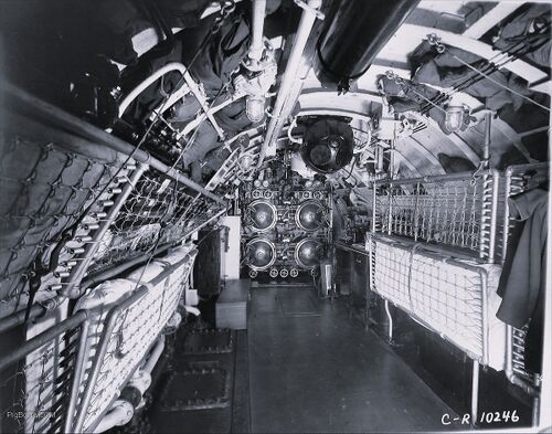
Ther are no torpedoes in this photo since the T-3 was brought back into commission strictly to test the German M.A.N. diesels with no intention for it to return as a fighting vessel. The space is being utilized for berthing and all the equipment for storing torpedoes has been removed.
The large black object in the overhead of the room is the motor for running the anchor and deck capstan. On the left in the photo, above the bunks is a valve manifold that is believed to be the forward fuel filling and transfer manifold. At the very top of the photo, above the light, is the transfer box for the control rod for the bow planes. At this point the mechanical torque from the rod is turned 90 degrees and exits the pressure hull through bushings and a gland seal. Stuffed in the overhead behind pipes and wires are life jackets.
Forward of the bunks on the right side of the photo is a desk with a typewriter on it. It was first thought this was used for radio equipment but after examining the photo of the radio space that opinion has been discarded. It could have been used for maintaining ships records by the ships clerk or Yeoman, or maybe have been installed for use during the trials. A portable electric space heater seen on the deck by the table leg and bottom torpedo tube door.
Photo courtesy of Sean Hert via Mike Mohl and Navsource.org.
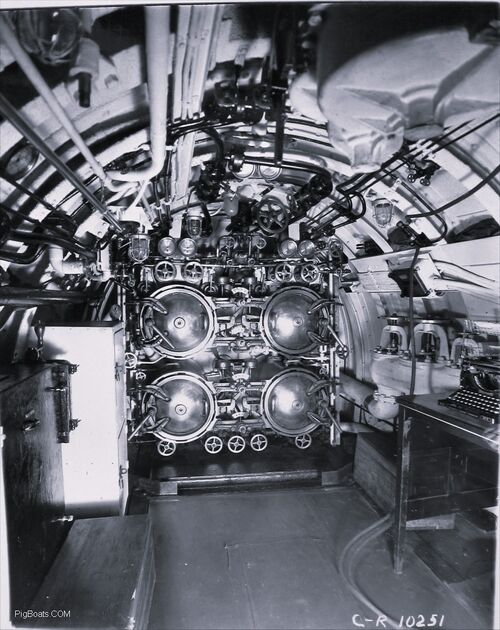
The large valves and piping seen on the right, forward of the desk, are supposed to be part of the Trim and Drain system used for moving trimming water, (read weight), from and to the forward trim tank or to other tanks or from or to sea from the submarine. This system also combined the ability to pump the bilges.
The torpedo tubes are numbered, top to bottom and right to left. Looking at the photo the top tube on the right is number 1. The top tube on the left is number 2. The bottom tube on the right is number 3 and the bottom left is number 4. This numbering system is still in use today.
Above the top tier of tube doors are seen the manual tube firing levers. One each for each tube and be seen at the 10 o'clock and 2 o'clock positions above each door. The round valve handles above the doors separate the manual firing levers. The handles point up. When the command to fire is given the valve is pulled. If the electrical firing control in the control room fails, the manual lever will actuate the impulse air to the tube and eject the torpedo.
Between the tubes is a small arc shaped plate and just below these is a stub end for a handle. A large lever is placed over this and turned to open and close the outer torpedo tube shutter doors used to fair the tube openings with the hull and protect the outer doors from damage.
Photo courtesy of Sean Hert via Mike Mohl and Navsource.org.
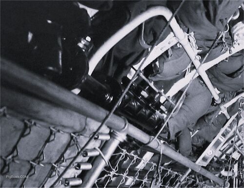
Photo courtesy of Sean Hert via Mike Mohl and Navsource.org.
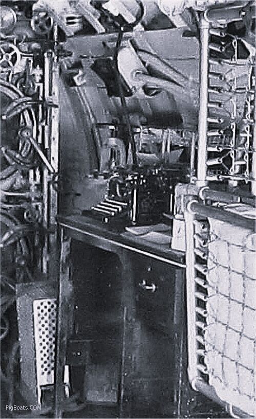
Photo courtesy of Sean Hert via Mike Mohl and Navsource.org.
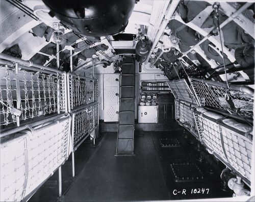
The large black object in the overhead is the capstan motor. Just to the right of the ladder in the overhead is an oxygen flask. Just to the right of that is the end of the bow planes control rod. Life jackets are stuffed into available spaces throughout the overhead.
Behind and above the tipped up bunks on the right is the forward fuel filling manifold.
At the far end of the compartment is a desk area. A reference library and the ship's safe. Stacked on top of the safe are containers of soda lime that in time of need can be open and spread on bunks or the deck to absorb CO2 from the atmosphere. Barely seen on the deck behind the bunks on the left side is another portable electric space heater. There is a non-watertight door behind the ladder that leads to the officer's berthing and wardroom.
Photo courtesy of Sean Hert via Mike Mohl and Navsource.org.
Radio Room
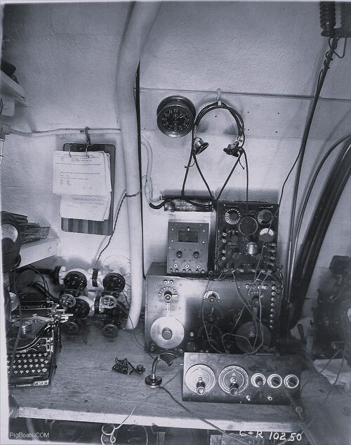
Photo courtesy of Sean Hert via Mike Mohl and Navsource.org.
Wardroom and Officer's Berthing
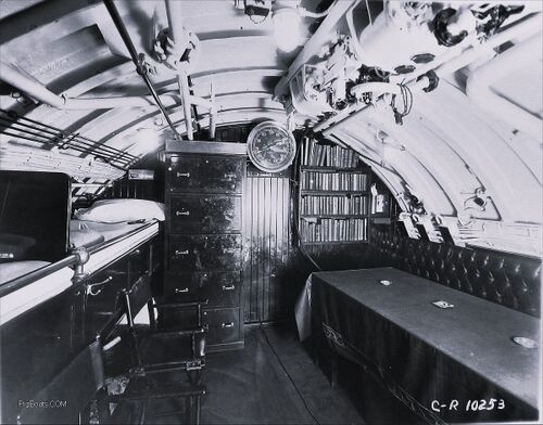
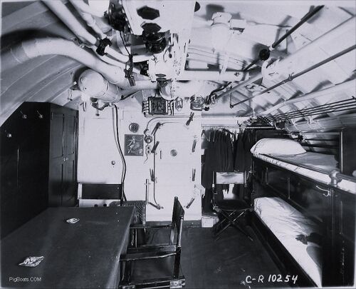
This view is looking forward. Over the door to the torpedo room proper is a depth gauge. It only measures to 100 feet though the actual test depth of the T-class was 150 feet. Folding camp chairs were used for general seating and for eating at the wardroom table. Ashtrays, a.k.a. "butt kits", are placed down the center of the table since smoking very common in this time period.
The table itself is covered by a heavy tablecloth, most probably dark green in color as that is a traditional color for this cloth in the U.S. Navy. The cloth has a fancy trim around the edge, possibly gold in color. Hanging in the overhead is an electrical cord with a socket fitting, probably for a clothing iron to press clothing, using the wardroom table as the ironing surface.
The dark rod seen in the overhead to left is a curtain rod to block off the berths from the rest of the space. The rings for hanging this curtain can be seen at the far end of the rod. Next to it is the drive shaft for the bow planes.
We are speculating that the two hydraulic motors in the overhead are used to lift spare torpedo bodies and warheads stored under the wardroom decks.
Photo courtesy of Sean Hert via Mike Mohl and Navsource.org.
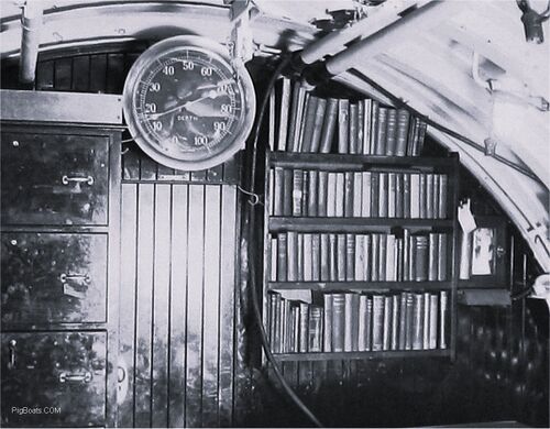
Books in the ships library used for reference are stored in the wardroom. Next to the depth gauge a large power cord can be seen draped over several pipes. This is for one of the numerous portable space heaters. The heater is hidden by the table. A reading lamp can be seen to the right of the bookcase.
Photo courtesy of Sean Hert via Mike Mohl and Navsource.org.
On either side of this door are, to the right, an area for hanging uniforms. In the earlier T-class these were separate lockers and on the opposite side of the door. To the left of the watertight door is a door that leads to the officer's head.
To the left of the door are a number of items. A large pipe running over the door and down the left side to a bell is a speaking tube. The bell is to let the wardroom know someone wants to talk. Below the bell are the compartment light switches. Below these, close to the bottom of the door is a dogging wrench used to tighten the dogs on the watertight door as tight as possible.
To the left of these is a bit of 1920's art or maybe "cheesecake". Above is a Chelsea clock, the time is 2:35, (probably PM). The power cord for a portable space heater is seen next to the left. The heater is seen at the end of the table.
The door to the officer's head is next. A large varnished mahogany closet is at the left.
Photo courtesy of Sean Hert via Mike Mohl and Navsource.org.
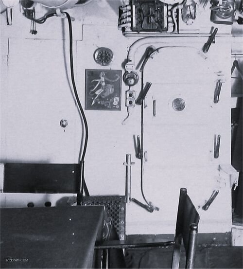
Photo courtesy of Sean Hert via Mike Mohl and Navsource.org.
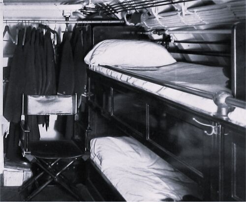
Photo courtesy of Sean Hert via Mike Mohl and Navsource.org.
Battery Compartment and Crew's Berthing
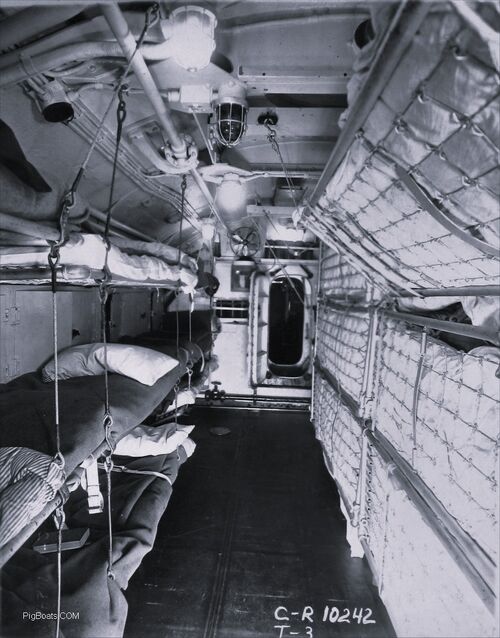
This photo is looking forward up the port side of the crew's berthing compartment. Through the door at the far end is the officer's berthing and wardroom space.
The deck is the covering over the battery. It is shellacked and painted canvas stretched over wood boards fastened over the batteries. The decks have been reported to have been colored green. All the bunks and other equipment is suspended from the overhead so as to not have any punctures on the canvas decking.
If you look closely through the watertight door into the wardroom you will see that it is a double "airlock" type door. There is a space of about 4 or 5 feet between the doors. This space accommodates officer's hanging lockers and the officer's head. There is a second head in the engine room for the crew. The large shaft in the overhead is the drive rod for the bow planes.
Photo courtesy of Sean Hert via Mike Mohl and Navsource.org.
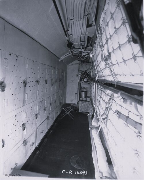
Lockers for clothing and personal items line the left side of the photo. At the far end of the compartment the square box with holes is a portable electric space heater. The power cable for the heater bows out to the left of the unit and drapes over the battery blower motor and proceeds to an outlet in the overhead.
There is a folding camp stool on the deck near the heater. The large round object on the bulkhead is one of the ventilation blowers for the battery well below the deck. When being charged, the battery cells produced highly flammable hydrogen gas. These blowers removed the hydrogen and vented it overboard.
Photo courtesy of Sean Hert via Mike Mohl and Navsource.org.
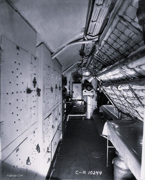
At the aft end of the compartment is a battery well ventilation blower. What looks to maybe be a gyrocompass is in the left corner of the space behind the railing. On the deck a large connector box seems to have very large power cables associated with it, no doubt coming from the battery. A power cord snakes across the deck, probably for the lights used in making this photo.
Photo courtesy of Sean Hert via Mike Mohl and Navsource.org.
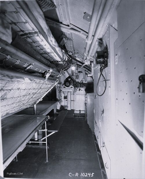
The hold downs for stretching and holding the canvas deck in place can be seen at the bottom of the photo below the lockers. Some sort of meter, probably associated with the battery, is on the bulkhead, and it looks to have a handheld device for using it.
Photo courtesy of Sean Hert via Mike Mohl and Navsource.org.
Galley
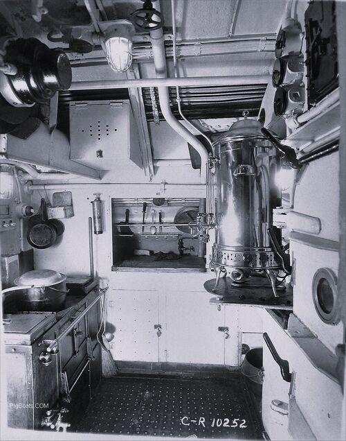
The galley doesn't have a look of being in use at this time. On the right is the coffee pot. To the left is the range with the oven. Directly across, in front of the camera, is the food preparation area.
Just below the coffee pot can be seen a large bolt. This seems to line up with a hole drilled in the large horizontal bar on the back of the watertight door just below the deadlight or "porthole". Probably used to hold the door open.
On the near side of the stove there appears to be a water boiler, but the glass sight tubes seem to be missing on the front of the boiler. Above the stove on the bulkhead is a storage box probably for spices like salt, pepper and the like. A hook full of frying pans hang from a hook hooked over a pipe that runs through the galley.
Almost unseen, a ring of keys hang from the coffee pot spout. A number of padlocks can be seen hanging from locker doors. Access to food was still tightly restricted in 1925, over fears of pilfering. On the deck, below the coffee pot is another large cooking pot that looks to be the twin of the one on the stove top.
Photo courtesy of Sean Hert via Mike Mohl and Navsource.org.
Control Room
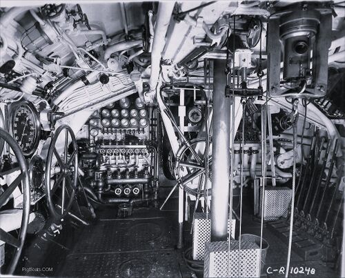
In the right center of the photo are the helm wheels. There are two. The forward wheel can just be seen as an arc on the left behind the angled chain guards. The wheels have long folding spoke extensions to assist in turning the wheel when in manual power. Normally the helm is power assisted by electric motors. Seen in the "V" of the chain guards is a compass repeater for steering a course. Behind the helm is the door in the bulkhead that leads into the galley space.
Scattered through the compartment, on the deck, are portable electric space heaters. Seen here as sheet metal boxes covered with holes.
On the far right side of the photo are the levers used for opening and closing the Kingston valves. These operated the covers that closed and sealed off the bottoms of the ballast tanks. To dive these were opened and then the vents on the top of the tanks was opened and this allowed water to flood the tank. When the tank was full the vents and the Kingstons were closed. To surface the Kingstons were opened and water forced out by air.
In the center right closest to the camera are the two periscopes. #1 scope is fully lowered, and #2 scope (closest to the camera) is fully raised, showing the eyepiece. These are raised and lowered by cables which can be seen running vertically in the photo. These cables were wound using electric motors. In later boats this was replaced by hydraulics.
Photo courtesy of Sean Hert via Mike Mohl and Navsource.org.
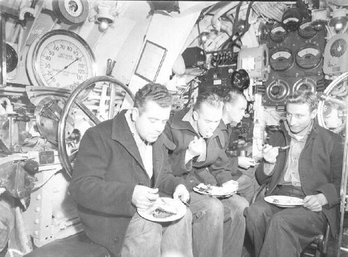
U.S. Navy photo
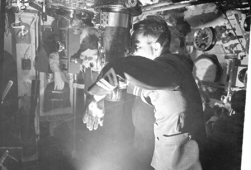
U.S. Navy photo
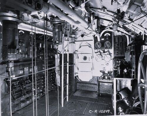
The ladder seen here is in its stored position. The actual access to the bridge is in the forward port side of the compartment in the area of the high pressure air manifold in the previous photo. It can't be seen because of the large main frame between it and the camera.
The door leads into the airlock that opens into the engine room. To the right of the door are large rheostats that are used to regulate electrical power from the batteries as it is fed to the motors. In later submarines this space was moved aft and placed into its own room.
On the very right side is a bench that holds a coffee pot and an old fashioned 'daffodil' style telephone. Below the bench are a number of unused motors and fans.
Photo courtesy of Sean Hert via Mike Mohl and Navsource.org.
Engine Room
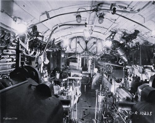
Above the door are two fuel "gravity tanks". Fuel for the engines was pumped up from the sump tank, through three fuel filters, (the quality of diesel fuel was still pretty iffy and contamination by dirt a possibility for fouling the engine fuel inlets), and into the tanks, where the force of gravity would keep a constant feed to the fuel racks. The tanks feed fuel from a line that sat about 3 to 4 inches off the bottom of the tank to the engines. This was to prevent and dirt of sludge from being picked up by the fuel intakes and delivered to the diesels.
Sight glasses to show the condition of the tanks can be seen on the front of them. The starboard tank show that the tank has been isolated from the port tank and is only about 1/3 full while the port tank is showing to be full. If the tanks were cross connected they would show the same level.
At deck level, to port and starboard, are the air compressors. Just forward of the port, (left), compressor is seen the engineering desk. It is used standing up and so has been installed at a slight angle. Above and to the left of the desk are several electrical panels, the purpose of which are not known. On the near side of the desk are several small trays with a high lip for holding small objects and preventing them from rolling off. The closer bench has a vice attached to it just to the right of the large can. The two engine order telegraphs are seen port and starboard above the air compressors.
Barely seen in the lower left and right in the photo are the fronts for the two Navy built BuEng/M.A.N. (Bureau of Engineering/Maschinfabrik Augsburg Nurnburg) diesel engines manufactured under license to the German design. The installation and trials of these engines was the whole reason for the re-commissioning of the T-3, to be used as an experimental vessel for these engines. The engines were supposed to improve the performance of this class of submarine, a "Fleet Submarine", able to keep up with the battleship fleet. They proved to be too unreliable to help these boats.
Photo courtesy of Sean Hert via Mike Mohl and Navsource.org.
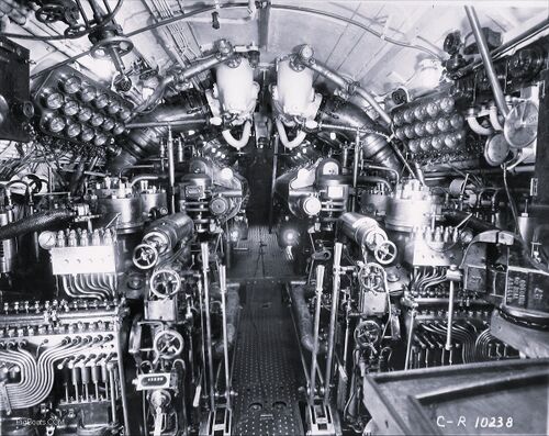
There are many interesting things in this photo. Working from the right side of the photo the first thing in the foreground is a "Massy Vice Co" number 27 made in Chicago. It has a swivel base with locking notches. This is a large vice meant for serious work.
Above the vice on right edge of the photo is the port engine order telegraph. To the left of this are a three tier bank of gauges for the air banks. There is a similar arrangement on the starboard side and a telegraph over the air compressor on that side. What the purpose of the rheostats above the telegraph is not known.
The next most obvious things seen in this photo are two air compressors. These can be clutched and declutched using one of the large levers seen of either side of the walkway.
Behind the air compressors are the M.A.N. diesels. These were big 2,350 horse power engines intended to drive the T-3 through the water, on the surface, at 20 to 21 knots with the goal of keeping up with the surface fleet battle line. These were connected through clutches to the motor/generators and the shafts to turn the propellers. Above the engines are the two massive air intake valves from the main induction for these engines. You can see in the overhead above the engines, like little dots, are lights for illuminating the compartment. At the far end is a ladder for exiting through the engine room hatch. These engines were not successful enough to warrant further use or production, although the test program yielded valuable data. Once the program was complete, the T-3 was promptly decommissioned and sent back to the reserve fleet before being scrapped in 1931.
Photo courtesy of Sean Hert via Mike Mohl and Navsource.org.
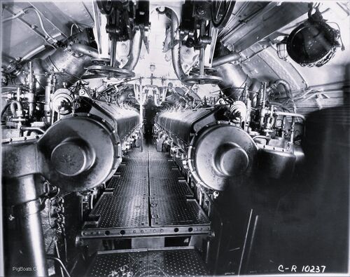
At midpoint the ladder to the deck through the engine room hatch is seen, this time on the left side of the passageway. In the foreground the two large valves hanging down are exhaust valves. This piping had large one-way valves in them to prevent seawater from backing back up into the engines.
Photo courtesy of Sean Hert via Mike Mohl and Navsource.org.
Motor Room/Auxiliary Machinery Room
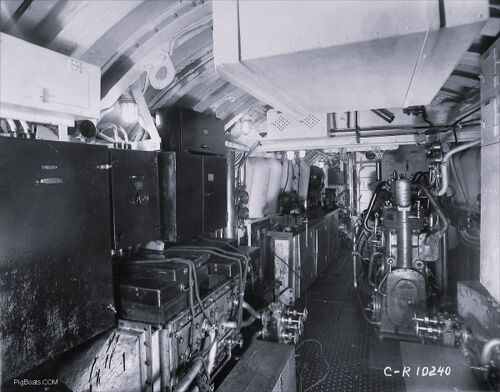
In this view from forward looking aft, on the left are electrical and storage cabinets and below them it appears to be a lube oil tank of some sorts. Strapped to the tank top, via ropes, are cases made of wood that are probably holding tools or instruments of some sort.
Seen on the right is a small diesel engine. It sits on the centerline of the submarine so you can see how narrow the sub is at this point. It is probably for providing power for battery charging and other power needs. The valve manifolds, seen port and starboard in the near foreground, are possibly for either fuel or water systems. Seen at left rear is a long work bench with a vice and other power tools. At the far end of the compartment is the door to an aft escape trunk.
Photo courtesy of Sean Hert via Mike Mohl and Navsource.org.
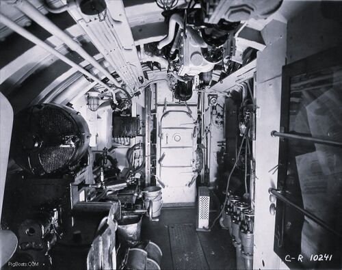
Photo courtesy of Sean Hert via Mike Mohl and Navsource.org.
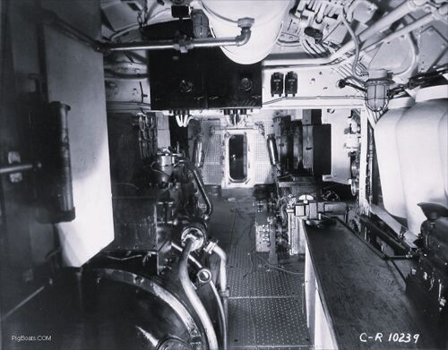
Photo courtesy of Sean Hert via Mike Mohl and Navsource.org.
Page created by:
Ric Hedman & David Johnston
1999 - 2023 - PigBoats.COM©
Mountlake Terrace, WA, Norfolk, VA
webmaster at pigboats dot com
