Dolphin Engine Room: Difference between revisions
Pbcjohnston (talk | contribs) Added photos |
Pbcjohnston (talk | contribs) Finished engine room |
||
| Line 22: | Line 22: | ||
<small>US Navy Photo Contributed by Roger Torgeson</small> | <small>US Navy Photo Contributed by Roger Torgeson</small> | ||
[[File:Red bar sub new 2.jpg]] | |||
[[File:Dolphin Engine Rm-1c.jpg|left|500px]] | |||
<div style="text-align: justify;"><span style="color:#00008B">Seen through the rungs of the ladder are the engine air inlet and exhaust outlet open/shut indicators plus shaft RPM counters. By the clock the photo was taken at 2:25PM on July 2, 1933. | |||
<small>US Navy Photo Contributed by Roger Torgeson</small> | |||
[[File:Red bar sub new 2.jpg]] | |||
[[File:Dolphin Engine Rm-1d.jpg|left|500px]] | |||
<div style="text-align: justify;"><span style="color:#00008B">The gauge board for the port engine. What each dial is used for is written on the face of each dial but is just beyond being able to be read. The valve handles at the bottom of the panel are for isolating the gauges. | |||
<small>US Navy Photo Contributed by Roger Torgeson</small> | |||
[[File:Red bar sub new 2.jpg]] | |||
[[File:Dolphin Engine Rm-2.jpg|left|500px]] | |||
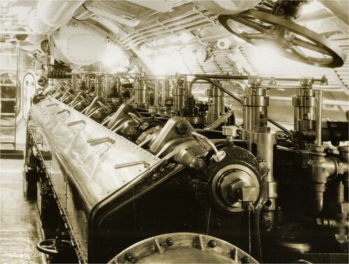
<div style="text-align: justify;"><span style="color:#00008B">The engine room looking forward. These engines were big and powerful, but heavy. Later diesels would be smaller and lighter, but produce more horsepower. In 1933 diesel engines as a concept were only about 20 years old. The technology was new and the industrial base was underdeveloped. That would soon change as the U.S. railroads got interested in converting their locomotives to diesel power. The Navy benefitted from that timely development. | |||
With both engines running at full power the noise level in this space was beyond comprehension. It was impossible to talk to other crew members, so they used a series of hand signals to communicate orders and instructions. | |||
<small>US Navy Photo Contributed by Roger Torgeson</small> | |||
[[File:Red bar sub new 2.jpg]] | |||
[[File:Dolphin Engine Rm-2b.jpg|left|500px]] | |||
<div style="text-align: justify;"><span style="color:#00008B">The starboard engine, looking forward. The large valve wheel in the overhead is most likely for the engine exhaust valve. | |||
<small>US Navy Photo Contributed by Roger Torgeson</small> | |||
[[File:Red bar sub new 2.jpg]] | |||
[[File:Dolphin Engine Rm-2c.jpg|left|500px]] | |||
<div style="text-align: justify;"><span style="color:#00008B">The port engine, looking forward. The shiny bar at an angle in the foreground is actually a "T" handled wrench slipped through a handhold. | |||
The large articulated rod in the upper left portion of the view is the mechanical linkage for the stern planes. It ran from the control room all the way aft to the aft torpedo room. If the electrical controls for the planes failed, they could still be operated through this mechanical linkage. | |||
<small>US Navy Photo Contributed by Roger Torgeson</small> | |||
[[File:Red bar sub new 2.jpg]] | |||
<center>[[Dolphin Generator Room|Generator Room/Galley/Chief's Mess]] | [[Dolphin Maneuvering/CPO/Motor Room|Maneuvering/CPO Berthing/Motor Room]]</center> | |||
[[File:Red bar sub new 2.jpg]] | [[File:Red bar sub new 2.jpg]] | ||
<center> | <center> | ||
Latest revision as of 16:51, 19 June 2023
Engine Room
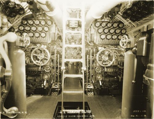
Second thing is the ladder from the deck access hatch passes through an opening into the lower engine room. Unfortunately, there are no photos of this lower engine room to allow us to know what was in this space.
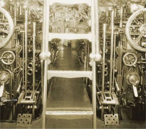
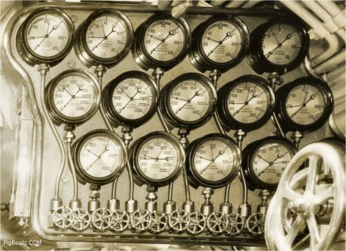
The next thing that becomes apparent is the forward faces of the two huge MAN diesels. These engines were license built MAN derivatives, with six cylinders running on a four stroke cycle. They were rated at 1,750 hp. These are direct drive engines, in that the crankshaft is connected directly to the propeller shaft through a clutch. The large wheels are most likely the throttles for increasing and decreasing the engine speeds. The gauges give vital information into the performance of all the cylinders and pressures.
Flanking the ladder, at the front of the engines, are two large clutch handles for engaging and disengaging the shafts from the engines. Note the angled foot plates for the Motor Machinist Mates (later to become Enginemen) to brace a foot against to gain the leverage needed to pull the levers.
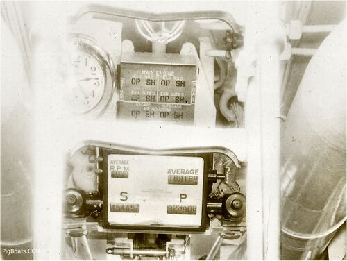
Seen through the rungs of the ladder are the engine air inlet and exhaust outlet open/shut indicators, plus shaft RPM counters.
US Navy Photo Contributed by Roger Torgeson
US Navy Photo Contributed by Roger Torgeson
US Navy Photo Contributed by Roger Torgeson
US Navy Photo Contributed by Roger Torgeson

With both engines running at full power the noise level in this space was beyond comprehension. It was impossible to talk to other crew members, so they used a series of hand signals to communicate orders and instructions.
US Navy Photo Contributed by Roger Torgeson
US Navy Photo Contributed by Roger Torgeson
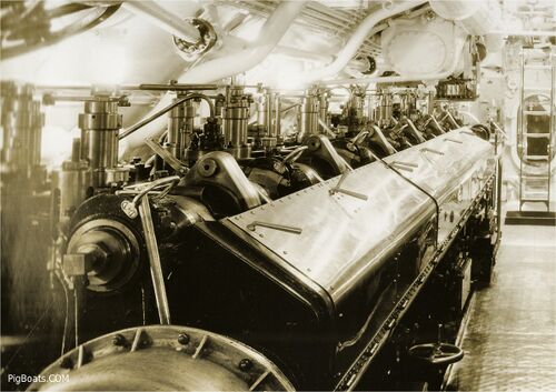
The large articulated rod in the upper left portion of the view is the mechanical linkage for the stern planes. It ran from the control room all the way aft to the aft torpedo room. If the electrical controls for the planes failed, they could still be operated through this mechanical linkage.
US Navy Photo Contributed by Roger Torgeson
Page created by:
Ric Hedman & David Johnston
1999 - 2023 - PigBoats.COM©
Mountlake Terrace, WA, Norfolk, VA
webmaster at pigboats dot com
