S-20: Difference between revisions
Pbcjohnston (talk | contribs) Various caption updates |
Pbcjohnston (talk | contribs) Added new Header |
||
| (3 intermediate revisions by the same user not shown) | |||
| Line 1: | Line 1: | ||
[[File:S- | [[File:New Header EB S-boats.jpg]] | ||
__TOC__ | __TOC__ | ||
=== <big>Design and Construction Notes</big> === | === <big>Design and Construction Notes</big> === | ||
<div style="text-align: justify;"><span style="color:#00008B">S-20 started life as a standard EB design Quincy built unit of the S-class. She served in her original guise until March 1924 when she was taken in hand for an 11 month yard period that heavily modified her for experimental program to see if the overall performance of the class could be improved. The Navy's performance needs for submarines were constantly expanding, and until new boats with better capabilities could be designed and built, the department was desirous to see if the S-boats could fill the gap. | <div style="text-align: justify;"><span style="color:#00008B">S-20 started life as a standard EB design Quincy built unit of the S-class. She served in her original guise until March 1924 when she was taken in hand for an 11 month yard period that heavily modified her for an experimental program to see if the overall performance of the class could be improved. The Navy's performance needs for submarines were constantly expanding, and until new boats with better capabilities could be designed and built, the department was desirous to see if the S-boats could modified to fill the gap. | ||
The low amount of reserve buoyancy in the bow for the EB design caused them to burrow into the waves while running at high speed on the surface, making them wet boats in anything other than calm seas. The first modification made was to the S-20's bow. Gone was the straight up and down chisel bow with its characteristic hawse pipe. It was replaced with a curved, raked bow with a outward upper flare. Hidden inside was a bow buoyancy tank. These features were intended to make the bow ride up and over a wave instead of burrowing into one. The widened fore deck required the modification of the bow planes operating system, moving the planes slightly outboard. This also eliminated the distinctive slab-sided angular fairings in front of the bow plane pivots. This new bow shape came to be known as the "fleet bow" and would form the basis of the design for the [[V-1 Class|'''V-1 class bow''']]. | The low amount of reserve buoyancy in the bow for the EB design caused them to burrow into the waves while running at high speed on the surface, making them wet boats in anything other than calm seas. The first modification made was to the S-20's bow. Gone was the straight up and down chisel bow with its characteristic hawse pipe. It was replaced with a curved, raked bow with a outward upper flare, or sheer. Hidden inside was a bow buoyancy tank. These features were intended to make the bow ride up and over a wave instead of burrowing into one. The widened fore deck required the modification of the bow planes operating system, moving the planes slightly outboard. This also eliminated the distinctive slab-sided angular fairings in front of the bow plane pivots. This new bow shape came to be known as the "fleet bow" and would form the basis of the design for the [[V-1 Class|'''V-1 class bow''']]. The remainder of the superstructure was rebuilt and widened. | ||
In an effort to expand the range of the boat, S-20 was fitted with external "saddle" fuel tanks attached to the outer hull on each side amidships. These seawater compensated tanks carried an extra 5,889 gallons (22,292 liters) of diesel fuel. | In an effort to expand the range of the boat, S-20 was fitted with external "saddle" fuel tanks attached to the outer hull on each side amidships. These seawater compensated tanks carried an extra 5,889 gallons (22,292 liters) of diesel fuel. | ||
| Line 12: | Line 12: | ||
While the modifications did indeed work, they did not work well enough to overcome the basic limitations of the EB design S-class boats. They were also expensive, and a budget minded Navy could not justify the additional expense of modifying any more boats. A proposed 1926 scheme to modify all of the existing EB design S-boats in a similar fashion was not approved, in part due to the experience with S-20. | While the modifications did indeed work, they did not work well enough to overcome the basic limitations of the EB design S-class boats. They were also expensive, and a budget minded Navy could not justify the additional expense of modifying any more boats. A proposed 1926 scheme to modify all of the existing EB design S-boats in a similar fashion was not approved, in part due to the experience with S-20. | ||
In 1931 S-20 became an engineering trials ship. Over the course of the next 14 years she tested a variety of different propulsion technologies. Some of the engines she had for only a few months of testing, others for several years. S-20 retained her original NELSECO 8-EB-15 direct drive engine and drive train on the port shaft, but her starboard engine was changed several times during this period to test new configurations. She even tested a diesel electric arrangement on that starboard shaft | In 1931 S-20 became an engineering trials ship. Over the course of the next 14 years she tested a variety of different propulsion technologies. Some of the engines she had for only a few months of testing, others for several years. S-20 retained her original NELSECO 8-EB-15 direct drive engine and drive train on the port shaft, but her starboard engine was changed several times during this period to test new configurations. She even tested a diesel electric arrangement on that starboard shaft. Some of these engines included:<br> | ||
•German MAN 600 bhp diesel direct (1931)<br> | •German MAN 600 bhp diesel direct (1931)<br> | ||
•MAN W6V 28/38 | •MAN W6V 28/38 700 bhp diesel electric (1932)<br> | ||
•Sun Shipbuilding 685 bhp, six cylinder inline diesel electric (1932?)<br> | •Sun Shipbuilding 685 bhp, six cylinder inline diesel electric (1932?)<br> | ||
•Electric Boat 16VM1 635 bhp diesel electric (1933)<br> | •Electric Boat 16VM1 635 bhp diesel electric (1933)<br> | ||
In 1945, near the end of the war, S-20 ran trials for a prototype snorkel head valve. This particular prototype was not connected to the engine room ventilation in any way. It was intended to test water flow around the snorkel head and test the operation of an early design of the head valve, which was intended to shut when the head dipped below the waves. The data gained from the S-20 tests was later incorporated into a working design, which was installed for initial testing on the [[R-6|'''USS R-6 (SS-83)''']] in August, 1945 in Florida waters. Much more work was needed to refine the design for fleet use, and the first operational model was installed on the [http://www.navsource.org/archives/08/08482.htm '''USS Irex (SS-482)'''] in 1947. The snorkel was a key piece of technology that came into heavy use during the post-war era, but was just a little too late for WWII. | In 1945, near the end of the war, S-20 ran trials for a prototype snorkel head valve (see below). This particular prototype was not connected to the engine room ventilation in any way. It was intended to test water flow around the snorkel head and test the operation of an early design of the head valve, which was intended to shut when the head dipped below the waves, preventing flooding. The data gained from the S-20 tests was later incorporated into a working design, which was installed for initial testing on the [[R-6|'''USS R-6 (SS-83)''']] in August, 1945 in Florida waters. Much more work was needed to refine the design for fleet use, and the first operational model was installed on the [http://www.navsource.org/archives/08/08482.htm '''USS Irex (SS-482)'''] in 1947. The snorkel was a key piece of technology that came into heavy use during the post-war era, but was just a little too late for WWII. | ||
Although she never made a war patrol, S-20 proved to be very useful to the Submarine Service and she was honorably decommissioned and scrapped just as the war was ending in 1945.</div> | Although she never made a war patrol, S-20 proved to be very useful to the Submarine Service and she was honorably decommissioned and scrapped just as the war was ending in 1945.</div> | ||
| Line 27: | Line 27: | ||
=== <big>Exterior Photos</big> === | === <big>Exterior Photos</big> === | ||
[[File:S-20 locks.jpg|left|500px]] | [[File:S-20 locks.jpg|left|500px]] | ||
<div style="text-align: justify;"><span style="color:#00008B">S-20 on one of her visits to the Panama Canal, likely in March 1923. She is in one of the lock systems designed to raise or lower the boat to match the different heights of the canal. There is just enough detail to show this is Panama. At the top left of the photo can be seen one of the "donkey" locomotives used to pull the vessels into and through the locks. | <div style="text-align: justify;"><span style="color:#00008B">S-20 on one of her visits to the Panama Canal, likely in March 1923. The time frame is prior to her March 1924 to February 1925 conversion when she received a new raked bow. | ||
She is in one of the lock systems designed to raise or lower the boat to match the different heights of the canal. There is just enough detail to show this is Panama. At the top left of the photo can be seen one of the "donkey" locomotives used to pull the vessels into and through the locks. | |||
A lock gate can be seen on the left and behind the submarine is another gate. The lock behind is higher than the shown lock which means the submarine is descending to sea level. She may be in a center lock or the last lock. It is unclear which direction she is proceeding. | A lock gate can be seen on the left and behind the submarine is another gate. The lock behind is higher than the shown lock which means the submarine is descending to sea level. She may be in a center lock or the last lock. It is unclear which direction she is proceeding. | ||
<small>Photo from an original post card in the private collection of Ric Hedman</small> | <small>Photo from an original post card in the private collection of Ric Hedman</small> | ||
| Line 45: | Line 45: | ||
[[File:S-20 port gray.jpg|left|500px]] | [[File:S-20 port gray.jpg|left|500px]] | ||
<div style="text-align: justify;"><span style="color:#00008B">S-20 underway in the Canal Zone, late 1920's. The upward sweep (called " | <div style="text-align: justify;"><span style="color:#00008B">S-20 underway in the Canal Zone, late 1920's. The upward sweep (called "sheer") of the bow is apparent here. The saddle tanks are just visible in this photograph, amidships just above the wave and below the superstructure. | ||
<small>USN photo # NH 94167 via NHHC.</small> | <small>USN photo # NH 94167 via NHHC.</small> | ||
Latest revision as of 19:13, 17 March 2025
Design and Construction Notes
The low amount of reserve buoyancy in the bow for the EB design caused them to burrow into the waves while running at high speed on the surface, making them wet boats in anything other than calm seas. The first modification made was to the S-20's bow. Gone was the straight up and down chisel bow with its characteristic hawse pipe. It was replaced with a curved, raked bow with a outward upper flare, or sheer. Hidden inside was a bow buoyancy tank. These features were intended to make the bow ride up and over a wave instead of burrowing into one. The widened fore deck required the modification of the bow planes operating system, moving the planes slightly outboard. This also eliminated the distinctive slab-sided angular fairings in front of the bow plane pivots. This new bow shape came to be known as the "fleet bow" and would form the basis of the design for the V-1 class bow. The remainder of the superstructure was rebuilt and widened.
In an effort to expand the range of the boat, S-20 was fitted with external "saddle" fuel tanks attached to the outer hull on each side amidships. These seawater compensated tanks carried an extra 5,889 gallons (22,292 liters) of diesel fuel.
The aft superstructure skeg that ran from the after deck down to the rudder had been a source of frustration for the boat's crews. It was difficult to access to do maintenance and thus tended to rust quickly and become damaged. In some cases the skeg rusted so severely that it broke away in heavy seas. On S-20 the skeg was completely rebuilt to a profile much slimmer and smaller that the other boats. These three modifications gave S-20 a distinctive profile.
While the modifications did indeed work, they did not work well enough to overcome the basic limitations of the EB design S-class boats. They were also expensive, and a budget minded Navy could not justify the additional expense of modifying any more boats. A proposed 1926 scheme to modify all of the existing EB design S-boats in a similar fashion was not approved, in part due to the experience with S-20.
In 1931 S-20 became an engineering trials ship. Over the course of the next 14 years she tested a variety of different propulsion technologies. Some of the engines she had for only a few months of testing, others for several years. S-20 retained her original NELSECO 8-EB-15 direct drive engine and drive train on the port shaft, but her starboard engine was changed several times during this period to test new configurations. She even tested a diesel electric arrangement on that starboard shaft. Some of these engines included:
•German MAN 600 bhp diesel direct (1931)
•MAN W6V 28/38 700 bhp diesel electric (1932)
•Sun Shipbuilding 685 bhp, six cylinder inline diesel electric (1932?)
•Electric Boat 16VM1 635 bhp diesel electric (1933)
In 1945, near the end of the war, S-20 ran trials for a prototype snorkel head valve (see below). This particular prototype was not connected to the engine room ventilation in any way. It was intended to test water flow around the snorkel head and test the operation of an early design of the head valve, which was intended to shut when the head dipped below the waves, preventing flooding. The data gained from the S-20 tests was later incorporated into a working design, which was installed for initial testing on the USS R-6 (SS-83) in August, 1945 in Florida waters. Much more work was needed to refine the design for fleet use, and the first operational model was installed on the USS Irex (SS-482) in 1947. The snorkel was a key piece of technology that came into heavy use during the post-war era, but was just a little too late for WWII.
Although she never made a war patrol, S-20 proved to be very useful to the Submarine Service and she was honorably decommissioned and scrapped just as the war was ending in 1945.Exterior Photos
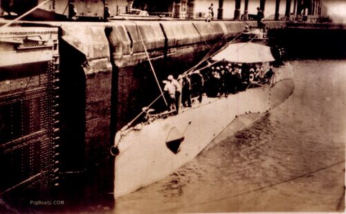
She is in one of the lock systems designed to raise or lower the boat to match the different heights of the canal. There is just enough detail to show this is Panama. At the top left of the photo can be seen one of the "donkey" locomotives used to pull the vessels into and through the locks.
A lock gate can be seen on the left and behind the submarine is another gate. The lock behind is higher than the shown lock which means the submarine is descending to sea level. She may be in a center lock or the last lock. It is unclear which direction she is proceeding.
Photo from an original post card in the private collection of Ric Hedman
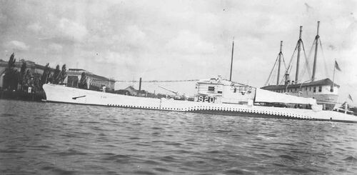
U.S. Navy photo
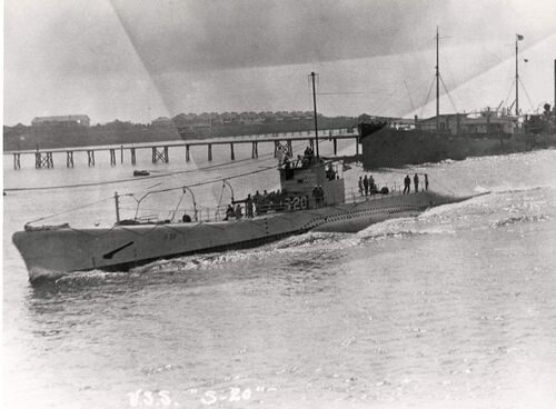
USN photo # NH 94167 via NHHC.
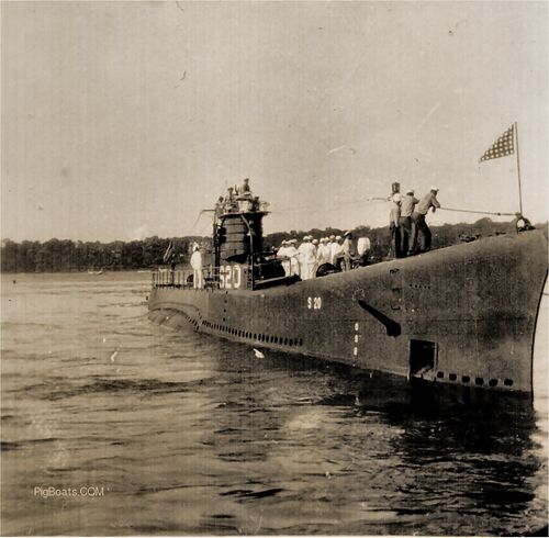
Note that the submarine is anchored. The anchor chain can be seen running out the anchor housing fairing. There are sailors in both whites and dungarees on deck. Those in whites are actually Midshipmen from the academy, aboard to get a feel for submarine operations. The shape and color of their headgear indicates their status as Midshipmen. Those not in whites are men from the crew and they comprise the inport duty section.
Photo in the private collection of Ric Hedman

U.S. Navy photo
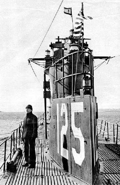
Photo provided by Stan Lintner, from the Lintner Family Collection. Used with permission.
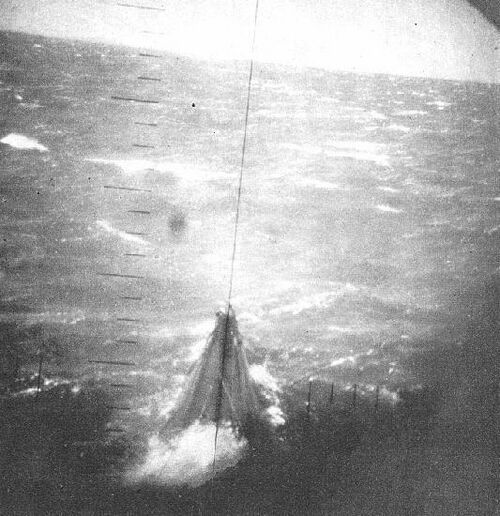
Photo provided by Stan Lintner, from the Lintner Family Collection. Used with permission.
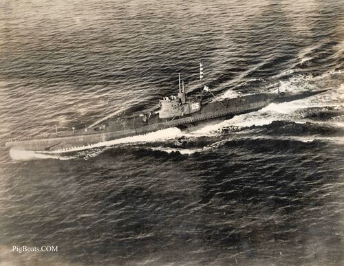
S-20 underway in the Atlantic, in 1945 near the end of the war. She was chosen to test a prototype shape for snorkel technology then just being developed by the USN, based on a Dutch design. The prototype can be seen mounted on a wire braced thin mast with two aft running braces aft of the fairwater. It was painted in a striped pattern for visibility.
The upper edge of the bridge fairwater has also received a wind venturi in a fashion similar to what the boats in the war zone were receiving. The venturi deflected wind up and over the heads of the bridge watchstanders, making their duty topside while surfaced a bit more tolerable and comfortable.
USN photo in the private collection of Ric Hedman.
Internal Photos
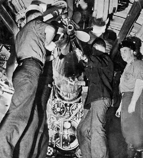
Photo provided by Stan Lintner, from the Lintner Family Collection. Used with permission.
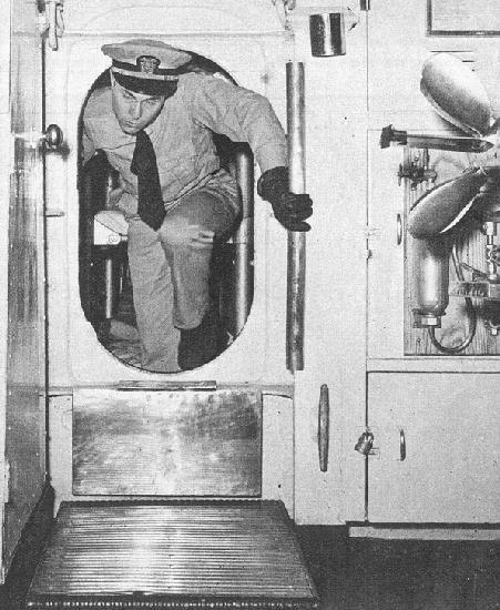
Photo provided by Stan Lintner, from the Lintner Family Collection. Used with permission.
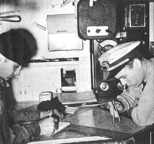
Photo provided by Stan Lintner, from the Lintner Family Collection. Used with permission.
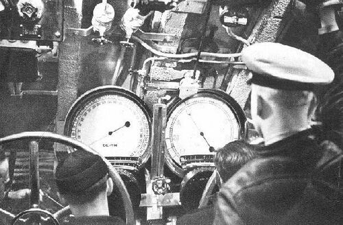
Photo provided by Stan Lintner, from the Lintner Family Collection. Used with permission.

Photo provided by Stan Lintner, from the Lintner Family Collection. Used with permission.
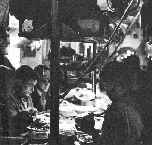
Photo provided by Stan Lintner, from the Lintner Family Collection. Used with permission.

Photo provided by Stan Lintner, from the Lintner Family Collection. Used with permission.
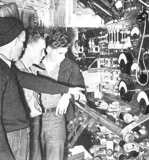
Photo provided by Stan Lintner, from the Lintner Family Collection. Used with permission.

Photo provided by Stan Lintner, from the Lintner Family Collection. Used with permission.

Photo provided by Stan Lintner, from the Lintner Family Collection. Used with permission.
Page created by:
Ric Hedman & David Johnston
1999 - 2023 - PigBoats.COM©
Mountlake Terrace, WA, Norfolk, VA
webmaster at pigboats dot com
