Dolphin FTR and WR: Difference between revisions
Pbcjohnston (talk | contribs) |
Pbcjohnston (talk | contribs) mNo edit summary Tag: Manual revert |
||
| (7 intermediate revisions by 2 users not shown) | |||
| Line 1: | Line 1: | ||
[[File:Header 169.jpg]] | [[File:Header 169.jpg]] | ||
=== The Windlass Room === | === The Windlass Room === | ||
<div style="text-align: justify;"><span style="color:#00008B"> | <div style="text-align: justify;"><span style="color:#00008B"> | ||
[[File:Dolphin WL Rm-1a.jpg|left|500px|<center>Windlass Room</center>]] | [[File:Dolphin WL Rm-1a.jpg|left|500px|<center>Windlass Room</center>]] | ||
Dolphin was the last submarine to have an enclosed dry compartment for the operating gear for the deck Windlass. In this room can be seen two of the Dolphin | Dolphin was the last submarine to have an enclosed dry compartment for the operating gear for the deck Windlass. In this room can be seen two of the Dolphin's life rings and the outboard motor for the ship's boat stored under the fore deck. The boat stored on the aft deck had an inboard engine. This compartment was accessed from the Forward Escape Trunk. | ||
<small>US Navy Photo Contributed by Roger Torgeson<br> | <small>US Navy Photo Contributed by Roger Torgeson<br> | ||
</small> | |||
</span> | </span> | ||
| Line 21: | Line 19: | ||
<div style="text-align: justify;"><span style="color:#00008B"> | <div style="text-align: justify;"><span style="color:#00008B"> | ||
[[File:Dolphin EH up-1.jpg|left|500px|<center>Forward Escape Hatch</center>]] | [[File:Dolphin EH up-1.jpg|left|500px|<center>Forward Escape Hatch</center>]] | ||
This is looking up | This is looking up from the deck in the forward torpedo room towards the bottom of the torpedo room escape hatch. The bottom hatch seems to oval in shape and offset at an angle. To the left are the torpedo tubes and the bow. To the right is aft. The glare coming down the hatch makes it hard to see any detail of the escape trunk itself. | ||
The articulated rod in the upper portion of the view is the mechanical linkage for the bow planes. | The articulated rod in the upper portion of the view is the mechanical linkage for the bow planes. | ||
<small>US Navy Photo Contributed by Roger Torgeson<br> | <small>US Navy Photo Contributed by Roger Torgeson<br> | ||
</small> | |||
[[File:Red bar sub new 2.jpg]] | [[File:Red bar sub new 2.jpg]] | ||
| Line 35: | Line 33: | ||
[[File:Dolphin TR fwd-1a.jpg|left|500px|<center></center>]] | [[File:Dolphin TR fwd-1a.jpg|left|500px|<center></center>]] | ||
The | The forward torpedo room looking forward. The view shows the forward half of the room including the four torpedo tubes and operating valves. | ||
The image was taken 13 months after the submarine had been commissioned. There are no torpedoes loaded at the time the picture was taken | The image was taken 13 months after the submarine had been commissioned. There are no torpedoes loaded at the time the picture was taken. She was at the Portsmouth Navy Yard from March 23, 1933 for final trials and acceptance and remained there until August 1, 1933. | ||
The ventilation ducting in the overhead splits around the | The ventilation ducting in the overhead splits around the torpedo room deck hatch. A ladder would attach to the forward side of the hatch. In this photo the ladder is laying on the top torpedo rack on the left or port side of the room. | ||
The rod seen running along the top of the compartment to the left is the mechanical linkage for the bow planes. | The rod seen running along the top of the compartment to the left is the mechanical linkage for the bow planes. | ||
<small>US Navy Photo Contributed by Roger Torgeson<br> | <small>US Navy Photo Contributed by Roger Torgeson<br> | ||
</small> | |||
[[File:Red bar sub new 2.jpg]] | [[File:Red bar sub new 2.jpg]] | ||
[[File:Dolphin TR fwd-2a.jpg|left|500px|<center></center>]] | [[File:Dolphin TR fwd-2a.jpg|left|500px|<center></center>]] | ||
Close up of the torpedo tube doors | Close up of the torpedo tube doors. The torpedo support stanchions in front of the tubes appear to be non-removable. But, on close analysis of the bases there appear to be bolts holding frames to the deck. | ||
The appearance that they look like they interfere with loading the lower tubes we think is a trick of angle with the camera. We believe the fore shortening effect of the camera makes them seem closer to the tubes and doors than they really are. | The appearance that they look like they interfere with loading the lower tubes we think is a trick of angle with the camera. We believe the fore shortening effect of the camera makes them seem closer to the tubes and doors than they really are. | ||
| Line 59: | Line 57: | ||
At the upper left portion of the view is the mechanical linkage for the bow planes. | At the upper left portion of the view is the mechanical linkage for the bow planes. | ||
<small>US Navy Photo Contributed by Roger Torgeson<br> | <small>US Navy Photo Contributed by Roger Torgeson<br></small> | ||
| Line 66: | Line 63: | ||
[[File:Dolphin TR aft-1a.jpg|left|500px|<center></center>]] | [[File:Dolphin TR aft-1a.jpg|left|500px|<center></center>]] | ||
The | The forward torpedo room looking aft. Bunks and torpedo storage racks can be seen to each side. There would be storage for 12 torpedoes here. That means one in each tube and two reloads for each tube. | ||
Note the torpedo loading hatch in the overhead just aft of the screened in enclosure. The wheel and the electronics on the aft bulkhead are for the Q series sonar heads with the | Note the torpedo loading hatch in the overhead just aft of the screened in enclosure. The wheel and the electronics on the aft bulkhead are for the Q series sonar heads with the shaft used to lower the heads below the keel for use. | ||
To the left is a small room. At this time we have no idea what this was for. Above is a small work area with a bench and vice plus a large electrical cabinet. | To the left is a small room. At this time we have no idea what this was for. Above is a small work area with a bench and vice plus a large electrical cabinet. | ||
| Line 74: | Line 71: | ||
The rod running across the face of the overhead locker in the upper right of the view is the mechanical linkage for the bow planes. | The rod running across the face of the overhead locker in the upper right of the view is the mechanical linkage for the bow planes. | ||
<small>US Navy Photo Contributed by Roger Torgeson<br> | <small>US Navy Photo Contributed by Roger Torgeson<br></small> | ||
[[File:Red bar sub new 2.jpg]] | [[File:Red bar sub new 2.jpg]] | ||
| Line 82: | Line 78: | ||
We call this the "Mystery Room". More research will probably tell us what this space was used for but until then this is the Mystery Room. It has a well used sliding door that has made scrape marks on the metal bulkhead and has an upper and lower ventilation screens at the inboard end. Part of a dial can be seen through the upper one. The overhead of the room forms a mezzanine with a large electrical cabinet and work bench with a vice. What was it used for? Unknown at this point. | We call this the "Mystery Room". More research will probably tell us what this space was used for but until then this is the Mystery Room. It has a well used sliding door that has made scrape marks on the metal bulkhead and has an upper and lower ventilation screens at the inboard end. Part of a dial can be seen through the upper one. The overhead of the room forms a mezzanine with a large electrical cabinet and work bench with a vice. What was it used for? Unknown at this point. | ||
Leaning against the door is a board that shows which officers are aboard and which are ashore. It also show who the Duty Officer and Duty Chief were and what the Duty Section was and something called the "Liberty Express". We are not familiar with this expression. It could possibly mean duty sections on liberty or not on duty. The board will be mounted to a bulkhead someplace or possibly taken topside while moored in port. | |||
<small>US Navy Photo Contributed by Roger Torgeson<br></small> | |||
[[File:Red bar sub new 2.jpg]] | |||
[[File:Dolphin TR aft-2d.jpg|left|500px]] | |||
A closeup of the Aboard/Ashore status board showing its arrangement. | |||
<small> | <small>U.S. Navy photo contributed by Roger Torgerson</small><br> | ||
[[File:Red bar sub new 2.jpg]] | [[File:Red bar sub new 2.jpg]] | ||
[[File:Dolphin TR aft-2a.jpg|left|500px|<center></center>]] | [[File:Dolphin TR aft-2a.jpg|left|500px|<center></center>]] | ||
The wheel and the electronics on the aft bulkhead are for the Q series sonar heads with the | The wheel and the electronics on the aft bulkhead are for the Q series sonar heads with the shaft used to lower the heads below the keel for use. | ||
<small>US Navy Photo Contributed by Roger Torgeson<br> | <small>US Navy Photo Contributed by Roger Torgeson<br></small> | ||
<!--............extra image code in case needed.........--> | <!--............extra image code in case needed.........--> | ||
| Line 109: | Line 110: | ||
[[File:Red bar sub new 2.jpg]] | |||
<center>[[Dolphin interior photos|Interior photos home page]] | [[Dolphin FB and Officer's Quarters|Forward Battery Compartment & Officer's Quarters]] </center> | |||
[[File:Red bar sub new 2.jpg]] | [[File:Red bar sub new 2.jpg]] | ||
<center> | <center> | ||
Latest revision as of 19:30, 15 June 2023
The Windlass Room
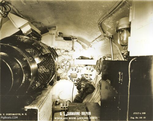
Dolphin was the last submarine to have an enclosed dry compartment for the operating gear for the deck Windlass. In this room can be seen two of the Dolphin's life rings and the outboard motor for the ship's boat stored under the fore deck. The boat stored on the aft deck had an inboard engine. This compartment was accessed from the Forward Escape Trunk.
US Navy Photo Contributed by Roger Torgeson
Forward Escape Trunk
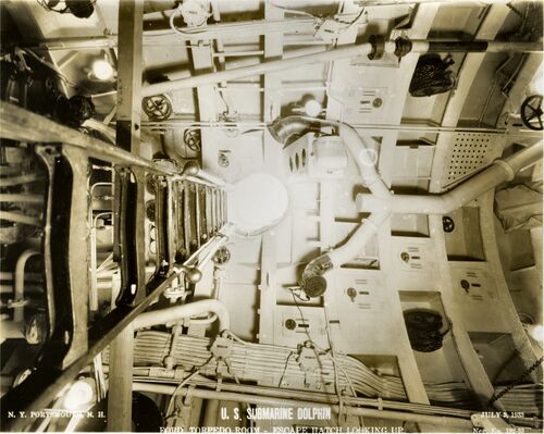
This is looking up from the deck in the forward torpedo room towards the bottom of the torpedo room escape hatch. The bottom hatch seems to oval in shape and offset at an angle. To the left are the torpedo tubes and the bow. To the right is aft. The glare coming down the hatch makes it hard to see any detail of the escape trunk itself.
The articulated rod in the upper portion of the view is the mechanical linkage for the bow planes.
US Navy Photo Contributed by Roger Torgeson
Forward Torpedo Room
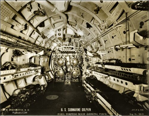
The forward torpedo room looking forward. The view shows the forward half of the room including the four torpedo tubes and operating valves.
The image was taken 13 months after the submarine had been commissioned. There are no torpedoes loaded at the time the picture was taken. She was at the Portsmouth Navy Yard from March 23, 1933 for final trials and acceptance and remained there until August 1, 1933.
The ventilation ducting in the overhead splits around the torpedo room deck hatch. A ladder would attach to the forward side of the hatch. In this photo the ladder is laying on the top torpedo rack on the left or port side of the room.
The rod seen running along the top of the compartment to the left is the mechanical linkage for the bow planes.
US Navy Photo Contributed by Roger Torgeson
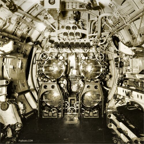
Close up of the torpedo tube doors. The torpedo support stanchions in front of the tubes appear to be non-removable. But, on close analysis of the bases there appear to be bolts holding frames to the deck.
The appearance that they look like they interfere with loading the lower tubes we think is a trick of angle with the camera. We believe the fore shortening effect of the camera makes them seem closer to the tubes and doors than they really are.
The curved lockers on the port side are unusual. We have not seen lockers shaped like this before.
If you look at the hull shape surrounding the tube doors you can see that the Navy was still building elliptical hull shapes. The hull is taller than it is wide.
At the upper left portion of the view is the mechanical linkage for the bow planes.
US Navy Photo Contributed by Roger Torgeson

The forward torpedo room looking aft. Bunks and torpedo storage racks can be seen to each side. There would be storage for 12 torpedoes here. That means one in each tube and two reloads for each tube.
Note the torpedo loading hatch in the overhead just aft of the screened in enclosure. The wheel and the electronics on the aft bulkhead are for the Q series sonar heads with the shaft used to lower the heads below the keel for use.
To the left is a small room. At this time we have no idea what this was for. Above is a small work area with a bench and vice plus a large electrical cabinet.
The rod running across the face of the overhead locker in the upper right of the view is the mechanical linkage for the bow planes.
US Navy Photo Contributed by Roger Torgeson
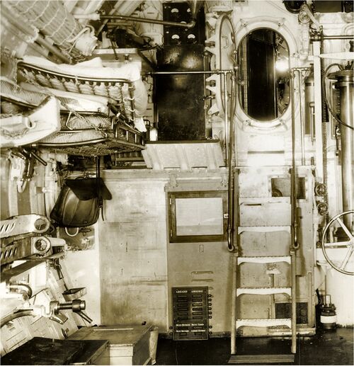
We call this the "Mystery Room". More research will probably tell us what this space was used for but until then this is the Mystery Room. It has a well used sliding door that has made scrape marks on the metal bulkhead and has an upper and lower ventilation screens at the inboard end. Part of a dial can be seen through the upper one. The overhead of the room forms a mezzanine with a large electrical cabinet and work bench with a vice. What was it used for? Unknown at this point.
Leaning against the door is a board that shows which officers are aboard and which are ashore. It also show who the Duty Officer and Duty Chief were and what the Duty Section was and something called the "Liberty Express". We are not familiar with this expression. It could possibly mean duty sections on liberty or not on duty. The board will be mounted to a bulkhead someplace or possibly taken topside while moored in port.
US Navy Photo Contributed by Roger Torgeson

A closeup of the Aboard/Ashore status board showing its arrangement.
U.S. Navy photo contributed by Roger Torgerson
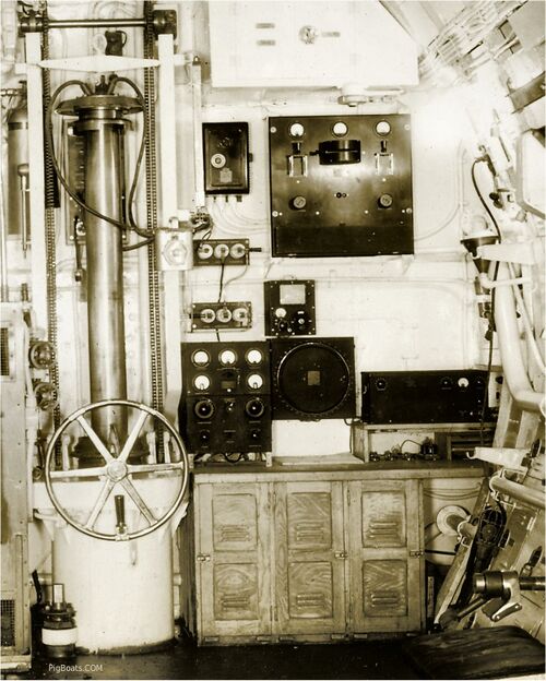
The wheel and the electronics on the aft bulkhead are for the Q series sonar heads with the shaft used to lower the heads below the keel for use.
US Navy Photo Contributed by Roger Torgeson
Page created by:
Ric Hedman & David Johnston
1999 - 2023 - PigBoats.COM©
Mountlake Terrace, WA, Norfolk, VA
webmaster at pigboats dot com
