General O-class photos: Difference between revisions
Pbcjohnston (talk | contribs) (Moved pictures) |
Pbcjohnston (talk | contribs) m (Added Rainbow link) |
||
| (4 intermediate revisions by the same user not shown) | |||
| Line 1: | Line 1: | ||
[[File:Header Plans.jpg]] | [[File:Header Plans.jpg]] | ||
[[File:O-boats with Rainbow.jpg|left|500px]] | |||
<div style="text-align: justify;"><span style="color:#00008B">Three O-boats of Submarine Division 10 moored outboard of the tender [https://www.navsource.org/archives/09/36/3607.htm '''USS Rainbow (Submarine Tender No. 7)'''] at a U.S. east coast or Caribbean port, approximately 1918-1919. The three submarines are (left to right) [[O-2|'''O-2''']], [[O-15|'''O-15''']], and [[O-16|'''O-16''']]. Note the differences in the bows of the O-2 (an Electric Boat design) and the O-15 and O-16 (both Lake designs). | |||
<small>Photo in the private collection of Ric Hedman</small> | |||
[[File:Red bar sub new.jpg]] | |||
[[File:O-Class moored in charleston.jpg|left|500px]] | |||
This photo shows five O-class submarines moored to a pier at Charleston, SC. in April of 1920. The subs were in the process of shifting their homeport from Philadelphia to Submarine Base Coco Solo, Panama and stopped here for a liberty call and fuel. From right to left the subs are O-12, O-16, O-14, O-13 and the last boat next to the pier is presumed to be the O-15 since the photo taker, George Petersen, was aboard the O-15. | |||
Laundry and bedding are hung out to dry on the life lines and the long wire radio antennas. On the pier the thick lines seen going over the edge of the dock are probably fuel hoses and the men are there to monitor them and help move them when needed. | |||
<small>Photo in the private collection of Ric Hedman</small> | |||
[[File:Red bar sub new.jpg]] | |||
[[File:O-class at guantanamo bay cuba.jpg|left|500px]] | [[File:O-class at guantanamo bay cuba.jpg|left|500px]] | ||
[[File:O- | Five Lake design O-class submarines moored to the docks at Guantanamo Bay, Cuba April 1920. The submarines are, left to right; O-14, O-12, O-15, O-13 and the O-11. There seems to other submarines moored behind these five subs but who they may be is unknown. | ||
[[File:O- | |||
<small>Photo in the private collection of Ric Hedman</small> | |||
[[File:Red bar sub new.jpg]] | |||
[[File:O-12 with others.jpg|left|500px]] | |||
Four O-class boats moored together at the Philadelphia Navy Yard, April 8, 1924, just two months before being decommissioned. The boats are sitting high in the water and have been already defueled with torpedoes removed. It is also possible that the heavy battery cells have been pulled out. The end of the line for these unpopular boats was near. | |||
<small>Photo in the private collection of Ric Hedman</small> | |||
[[File:Red bar sub new.jpg]] | |||
[[File:O-12 with others upclose.jpg|left|500px]] | |||
If you don't look close at the O-15 in the above photo, you will miss this interesting detail. Two members of her crew are lounging in the forward superstructure, taking a break from the work of preparing these boats for decommissioning. Based on how they are dressed, they were most likely chipping paint, a nasty, tedious, and uncomfortable job. | |||
<small>Photo in the private collection of Ric Hedman.</small> | |||
[[File:Red bar sub new.jpg]] | |||
[[File:O-boats in the canal locks.jpg|left|500px]] | |||
[[O-10|'''O-10 (SS-71)''']], [[O-8|'''O-8 (SS-69)''']], and [[O-4|'''O-4 (SS-65)''']] in one of the Panama Canal locks, 1924-1928. There are three more unidentified O-boats in the lock behind them. The boats are rafted together and are pulled into the lock as a unit by the "mule" locomotives that run on tracks on the lock walls. One mule can just be seen at the top of the photo. Many crewmembers are gathered topside in order to get some relief from the oppressive heat below. The retracted 3"/23 caliber deck gun can be seen just forward of the conning tower fairwater on all three boats. When retracted, only a portion of the barrel stayed above deck, looking something like a post or stanchion. | |||
<small>Photo in the private collection of David Johnston.</small> | |||
[[File:Red bar sub new.jpg]] | |||
[[File:O-9 torpedo room.jpg|left|500px]] | |||
The webmasters have some anecdotal evidence that this and the next five photos were taken aboard the [[O-9|'''O-9 (SS-70)''']], but we have no way to confirm this so we will call the identity as unidentified for now. We can say that these were definitely taken aboard an EB design O-class submarine. | |||
The noted difference between this photo and other O-class subs is that the torpedo tube doors have been painted white while others have been left polished brass. The EB design for the O-class had rotating torpedo tube bow caps. The bow cap had two openings. Only tubes diagonal from each other could be opened and fired before the bow cap needed to be rotated again. When the cap is in the closed position for all tubes, one hole is at the top of the cap behind the bow stem. The bottom hole is behind the lower portion of the bow stem. Rotating the cap opens one top tube and one lower tube diagonal from each other. | |||
The two tubes seen on the right are, from top to bottom, number 1 and number 3. The two tubes on the left are, from top to bottom, number 4 and number 2. Just to the left of tube number 4 and even with the top of the door is the cone shaped mouthpiece for the speaking tube from the control room. | |||
The row of wheels between the tubes are for opening and closing the torpedo tube outer doors on the outside of the submarine. In the center of the column of handles you can see a shiny "disk". This was an indicator that showed the position of the bow cap openings. To open the bow cap a long handle was attached to the spindle seen at the lower right corner of tube number 1. Rotating the handle spun the bow cap to the needed position. | |||
<small>Photo in the private collection of Ric Hedman</small> | |||
[[File:Red bar sub new.jpg]] | |||
[[File:O-9 torpedo rm port.jpg|left|500px]] | |||
A view of the torpedo room looking to port. Seen faintly on the tube doors are a "4" on the top tube and more clearly, a "2" on the bottom tube door. The speaking tube to the control room is distinctly visible in the left top center of the photo. | |||
The levers seen at the left side of the tube doors are for rotating the locking rings to hold the torpedo tube breech doors closed against sea pressure. This ring ensured an equal force around the outer edge of the door and on its gasket seal. | |||
<small>Photo in the private collection of Ric Hedman</small> | |||
[[File:Red bar sub new.jpg]] | |||
[[File:O-9 control w gages.jpg|left|500px]] | [[File:O-9 control w gages.jpg|left|500px]] | ||
This photo shows the after port side of the control room bulkhead with a pyramid of pressure gages for the 500, 300, and 100 psi air systems. Also, among these gages are the torpedo impulse tank repeater gauges. | |||
The operating wheel for the stern planes and part of the depth gauge are also seen. Each planesman had a depth gauge in front of them. (The wheel for the bow planes would be to the right and is out of the photo.) Below the pyramid of gauges are the handwheels for an air manifold. | |||
The cluster of gages on the left are for the five air banks each containing six air flasks each. The gages are from left to right as follows: air bank #2, air bank #4 on the top, air bank #1, air bank #3, and air bank #5 on the bottom. Air bank #1 was located in the control room. Air bank #2 was split with three flasks in the control room and three flasks in the torpedo room. The rest of the air banks were also in the torpedo room, all in a space under the deck called the "air bottle well". The flasks in the control room were under the deck also in their own air bottle well. All these air banks are charged to 2500 psi and reduced to working pressures of 500 pounds, 300 pounds, 200 pounds, and 100 pounds. Diesel air start was 750 pounds. | |||
There is a row of small valves below the air bank gauges that isolate the gauges from the air banks. Below that are five valves that opened or closed the air banks. These have no handles. They are operated by a wrench, painted white, and hanging on the frame above and to the right of these valves. Normally there would be one, maybe two air banks on service and the rest held in reserve. One might be designated the "Captain's air bank" and not used unless ordered to do so by the Captain. | |||
<small>Photo in the private collection of Ric Hedman</small> | |||
[[File:Red bar sub new.jpg]] | |||
[[File:O-9 engine aft.jpg|left|500px]] | [[File:O-9 engine aft.jpg|left|500px]] | ||
An O-boat engine room looking aft between the NELSECO 6-EB-14 diesel engines. Air start levers are near the top of the photo, with engine throttles near the bottom. These engines all had exposed valve rocker arms which were a danger to a careless crewman. | |||
There is a watertight door leading to the motor room. There seems to be one or more extension cords coiled up and hung over one of the watertight door dogs. In normal at sea operations this would not be permitted. Doors and their fittings were to be unencumbered at all times. | |||
<small>Photo in the private collection of Ric Hedman</small> | |||
[[File:Red bar sub new.jpg]] | |||
[[File:O-9 engine fwd.jpg|left|500px]] | [[File:O-9 engine fwd.jpg|left|500px]] | ||
A view of an O-boat's NELSECO diesels looking forward. This gives a better view of the exposed valve rocker arms. When these engines were running the noise level was nothing short of deafening. | |||
<small>Photo in the private collection of Ric Hedman</small> | |||
[[File:Red bar sub new.jpg]] | |||
[[File:O-9 eng looking aft.jpg|left|500px]] | [[File:O-9 eng looking aft.jpg|left|500px]] | ||
This view is of an O-boat motor room looking aft. The large object in the center is the low pressure ballast pump and it was capable of 1500 gallon per minute at a 20 foot-pound head. It pumped water to and from the "main drain", a hollow duct keel that flooded or emptied the ballast tanks. The ballast tanks could also be filled by flood ports in the bottom of the hull and through a Kingston valve. The high pressure pump had a capacity of 200 gallons per minute at a 300 foot-pound head of pressure. | |||
What is thought to be the motor for the high pressure pump in this photo is missing the covering over the chain drive to what is probably the pump. The cover is clearly seen in the other photo above of the engine room looking aft. The cover was probably removed for maintenance. | |||
The two circular coolers for the high pressure air compressors are clearly seen. When air is compressed to higher pressures it becomes hot. Before it was directed to the air flasks for storage it needed to be cooled. The cooling was done by passing the air over coils with cool sea water pumped through them. Kind of the reverse of a hot water boiler. | |||
It is remarkable seeing how brightly lit the interior is. | |||
<small>Photo in the private collection of Ric Hedman</small> | <small>Photo in the private collection of Ric Hedman</small> | ||
Latest revision as of 17:21, 5 September 2024

Photo in the private collection of Ric Hedman
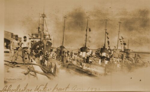
This photo shows five O-class submarines moored to a pier at Charleston, SC. in April of 1920. The subs were in the process of shifting their homeport from Philadelphia to Submarine Base Coco Solo, Panama and stopped here for a liberty call and fuel. From right to left the subs are O-12, O-16, O-14, O-13 and the last boat next to the pier is presumed to be the O-15 since the photo taker, George Petersen, was aboard the O-15.
Laundry and bedding are hung out to dry on the life lines and the long wire radio antennas. On the pier the thick lines seen going over the edge of the dock are probably fuel hoses and the men are there to monitor them and help move them when needed.
Photo in the private collection of Ric Hedman
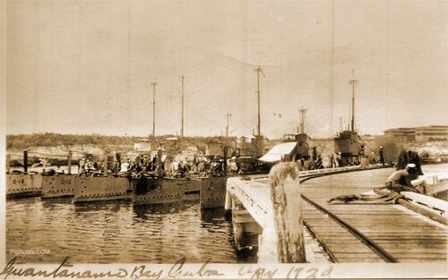
Five Lake design O-class submarines moored to the docks at Guantanamo Bay, Cuba April 1920. The submarines are, left to right; O-14, O-12, O-15, O-13 and the O-11. There seems to other submarines moored behind these five subs but who they may be is unknown.
Photo in the private collection of Ric Hedman
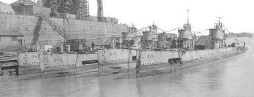
Four O-class boats moored together at the Philadelphia Navy Yard, April 8, 1924, just two months before being decommissioned. The boats are sitting high in the water and have been already defueled with torpedoes removed. It is also possible that the heavy battery cells have been pulled out. The end of the line for these unpopular boats was near.
Photo in the private collection of Ric Hedman
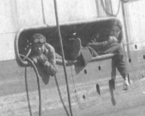
If you don't look close at the O-15 in the above photo, you will miss this interesting detail. Two members of her crew are lounging in the forward superstructure, taking a break from the work of preparing these boats for decommissioning. Based on how they are dressed, they were most likely chipping paint, a nasty, tedious, and uncomfortable job.
Photo in the private collection of Ric Hedman.
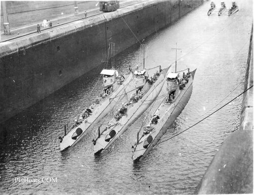
O-10 (SS-71), O-8 (SS-69), and O-4 (SS-65) in one of the Panama Canal locks, 1924-1928. There are three more unidentified O-boats in the lock behind them. The boats are rafted together and are pulled into the lock as a unit by the "mule" locomotives that run on tracks on the lock walls. One mule can just be seen at the top of the photo. Many crewmembers are gathered topside in order to get some relief from the oppressive heat below. The retracted 3"/23 caliber deck gun can be seen just forward of the conning tower fairwater on all three boats. When retracted, only a portion of the barrel stayed above deck, looking something like a post or stanchion.
Photo in the private collection of David Johnston.
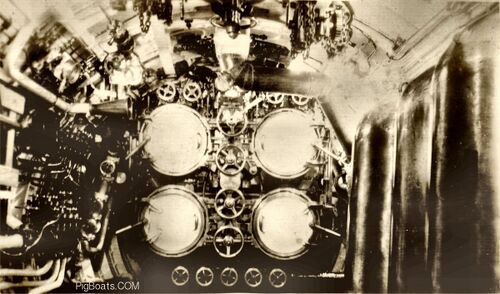
The webmasters have some anecdotal evidence that this and the next five photos were taken aboard the O-9 (SS-70), but we have no way to confirm this so we will call the identity as unidentified for now. We can say that these were definitely taken aboard an EB design O-class submarine.
The noted difference between this photo and other O-class subs is that the torpedo tube doors have been painted white while others have been left polished brass. The EB design for the O-class had rotating torpedo tube bow caps. The bow cap had two openings. Only tubes diagonal from each other could be opened and fired before the bow cap needed to be rotated again. When the cap is in the closed position for all tubes, one hole is at the top of the cap behind the bow stem. The bottom hole is behind the lower portion of the bow stem. Rotating the cap opens one top tube and one lower tube diagonal from each other.
The two tubes seen on the right are, from top to bottom, number 1 and number 3. The two tubes on the left are, from top to bottom, number 4 and number 2. Just to the left of tube number 4 and even with the top of the door is the cone shaped mouthpiece for the speaking tube from the control room.
The row of wheels between the tubes are for opening and closing the torpedo tube outer doors on the outside of the submarine. In the center of the column of handles you can see a shiny "disk". This was an indicator that showed the position of the bow cap openings. To open the bow cap a long handle was attached to the spindle seen at the lower right corner of tube number 1. Rotating the handle spun the bow cap to the needed position.
Photo in the private collection of Ric Hedman
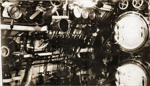
A view of the torpedo room looking to port. Seen faintly on the tube doors are a "4" on the top tube and more clearly, a "2" on the bottom tube door. The speaking tube to the control room is distinctly visible in the left top center of the photo.
The levers seen at the left side of the tube doors are for rotating the locking rings to hold the torpedo tube breech doors closed against sea pressure. This ring ensured an equal force around the outer edge of the door and on its gasket seal.
Photo in the private collection of Ric Hedman

This photo shows the after port side of the control room bulkhead with a pyramid of pressure gages for the 500, 300, and 100 psi air systems. Also, among these gages are the torpedo impulse tank repeater gauges.
The operating wheel for the stern planes and part of the depth gauge are also seen. Each planesman had a depth gauge in front of them. (The wheel for the bow planes would be to the right and is out of the photo.) Below the pyramid of gauges are the handwheels for an air manifold.
The cluster of gages on the left are for the five air banks each containing six air flasks each. The gages are from left to right as follows: air bank #2, air bank #4 on the top, air bank #1, air bank #3, and air bank #5 on the bottom. Air bank #1 was located in the control room. Air bank #2 was split with three flasks in the control room and three flasks in the torpedo room. The rest of the air banks were also in the torpedo room, all in a space under the deck called the "air bottle well". The flasks in the control room were under the deck also in their own air bottle well. All these air banks are charged to 2500 psi and reduced to working pressures of 500 pounds, 300 pounds, 200 pounds, and 100 pounds. Diesel air start was 750 pounds.
There is a row of small valves below the air bank gauges that isolate the gauges from the air banks. Below that are five valves that opened or closed the air banks. These have no handles. They are operated by a wrench, painted white, and hanging on the frame above and to the right of these valves. Normally there would be one, maybe two air banks on service and the rest held in reserve. One might be designated the "Captain's air bank" and not used unless ordered to do so by the Captain.
Photo in the private collection of Ric Hedman
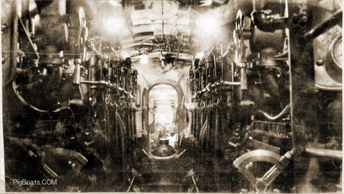
An O-boat engine room looking aft between the NELSECO 6-EB-14 diesel engines. Air start levers are near the top of the photo, with engine throttles near the bottom. These engines all had exposed valve rocker arms which were a danger to a careless crewman.
There is a watertight door leading to the motor room. There seems to be one or more extension cords coiled up and hung over one of the watertight door dogs. In normal at sea operations this would not be permitted. Doors and their fittings were to be unencumbered at all times.
Photo in the private collection of Ric Hedman
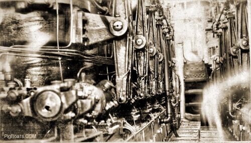
A view of an O-boat's NELSECO diesels looking forward. This gives a better view of the exposed valve rocker arms. When these engines were running the noise level was nothing short of deafening.
Photo in the private collection of Ric Hedman

This view is of an O-boat motor room looking aft. The large object in the center is the low pressure ballast pump and it was capable of 1500 gallon per minute at a 20 foot-pound head. It pumped water to and from the "main drain", a hollow duct keel that flooded or emptied the ballast tanks. The ballast tanks could also be filled by flood ports in the bottom of the hull and through a Kingston valve. The high pressure pump had a capacity of 200 gallons per minute at a 300 foot-pound head of pressure.
What is thought to be the motor for the high pressure pump in this photo is missing the covering over the chain drive to what is probably the pump. The cover is clearly seen in the other photo above of the engine room looking aft. The cover was probably removed for maintenance.
The two circular coolers for the high pressure air compressors are clearly seen. When air is compressed to higher pressures it becomes hot. Before it was directed to the air flasks for storage it needed to be cooled. The cooling was done by passing the air over coils with cool sea water pumped through them. Kind of the reverse of a hot water boiler.
It is remarkable seeing how brightly lit the interior is.
Photo in the private collection of Ric Hedman
Page created by:
Ric Hedman & David Johnston
1999 - 2023 - PigBoats.COM©
Mountlake Terrace, WA, Norfolk, VA
webmaster at pigboats dot com
