C-1
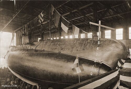
Photo NH 44578 courtesy of the NHHC.
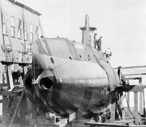
Octopus hauled out on the marine railway at the Fore River yard, probably in late 1906 or early 1907 as she was being prepared for the 1907 Navy sponsored competitive trials against the Simon Lake XV, a design by inventor Simon Lake. Octopus has not yet been accepted by the Navy as she is not flying the American flag. The building on the left in the photo is the building shed in which she was built.
Electric Boat's patented rotating bow cap for the muzzle doors of the torpedo tubes can clearly be seen here. The C-class had just two tubes. To open the muzzle ends of the tubes, the crew would manipulate controls inside the torpedo room that pushed the cap slightly forward to unseat the rubber gasket around each tube. A large handwheel inside the torpedo room would then be turned to rotate the cap so that the cutouts lined up with the tube muzzle ends. Once the tubes were shot, the crew would perform the opposite procedure: rotate the cap so that the cutouts in the cap were behind the upper and lower superstructure, then pull the lever back that seated the cap, creating a watertight seal on the muzzle end of the tube. EB would use the rotating cap feature on nearly all of its submarines up to the O-class of 1918. The two exceptions were the L and M-class. On the lower right on the bottom of the boat the port side bilge keel can be seen. This feature helped to reduce rolling while on the surface.
U.S. Navy photo
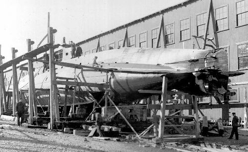
Another view of Octopus on the marine railway at the Fore River Shipbuilding Company, 1906-1907. The Octopus was the first twin propeller submarine commissioned into the U.S. Navy, starting a trend that would last until 1953.
U.S. Navy photo
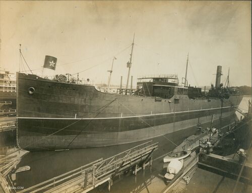
Octopus is shown here alongside a Fore River Shipbuilding dock in Quincy, MA., fall of 1907. Work to complete the Octopus for Navy acceptance is still ongoing, despite her having successfully passed the Navy demonstration several months prior.
The large ship next to her is the Steamship Everett, a collier built for the New England Coal & Coke Company that was delivered on October 19, 1907.
The ship in the rear is the SS Creole, Southern Pacific Steamship Lines (Morgan Line) that would begin service carrying passengers between the ports of New York and New Orleans. "100 hours of comfort" they bragged to the customers taking this trip. These place the date of the photo to slightly before that date.
Photo in the private collection of Ric Hedman.
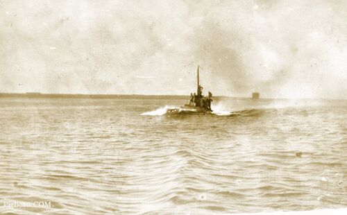
Octopus running at high speed, possibly in Narragansett Bay, Rhode Island, 1908-1909. This is likely Octopus' maximum speed of 11 knots. The men topside are only inches from the water and are in a precarious position if anything unexpected happens.
Photo from the collection of MMCM(SS) Rick Larson, USN (Ret.)
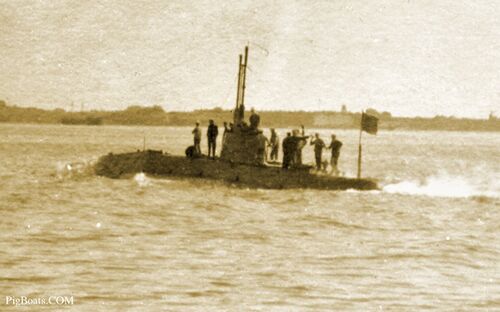
In another photo taken a few minutes after the one above, Octopus is seen entering a harbor, possibly Newport, R.I. or Norfolk, VA., 1908-1909. She is now at a much slower speed and her freeboard has increased slightly, making the men's position topside a little safer.
Photo from the collection of MMCM(SS) Rick Larson, USN (Ret.)
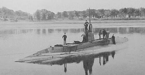
Octopus early in her career, probably 1906-1909, location unknown. Some small platforms have been temporarily rigged to the side of the superstructure fore and aft. Their purpose is unknown.
Photo in the private collection of Ric Hedman.
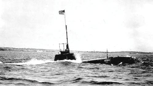
Octopus surfacing after a submerged run, possibly in Cape Cod Bay off Provincetown, MA., 1908-1910. She would still be running on the battery at this point, and would not start her engines until she was in full surface trim.
Photo in the private collection of Ric Hedman.
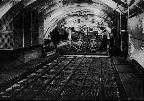
The battery compartment and torpedo tubes of the C-1, approximately 1912. The battery is an Edison Model 23-W, alkaline battery. It consists of 120 cells and had a capacity of 2550 Amps at a 3 hour discharge rate.
The wooden planks that cover the battery have been removed to show the individual plates and if you look closely you can see the small wood wedges (called cribbing) that hold the plates the designed distances from each other. When the decking is replaced it is screwed down and covered with a canvas that is shellacked down to make the deck waterproof. The shellack gives the decks a green color. With the deck in place the reload torpedoes and their storage skids would be in place on top of the deck.
The C-class submarines did not have individual watertight compartments. The entire boat, forward to aft, was one big compartment.
The screened cage protected the crew from falling into the electrical distribution boards with open fuses and knife switches. To the left of the cage, out of sight, is the location of where the stern planes were controlled. (no bow planes) The helm was controlled from the steering platform under the conning tower, also not seen in this photo.
U.S. Navy photo
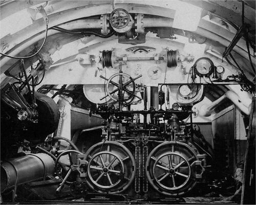
Detail from the above image. C-1 torpedo tubes showing the torpedo loading cable winches, sight glasses and associated piping and bow cap opening and closing hand wheel. A reload torpedo was positioned in front of the open tube door and a cable reeved through the pulley over the top center of each door from the winches seen above, and then to the rear of the torpedo.
On the outboard side of each winch drum are engaging handles to lock the drums onto a rotating shaft so you could only turn the selected winch drum and not the other. There is a long shaft running to what must have been a turning handle on the port side of the submarine but is obscured by anchor windlass motor gearing.
To the right of the starboard winch drum you can see an early interior communication sound powered phone system. It isn't clear if there are two handsets for listening but most likely you spoke into one and listened on the other. The cabling for these seems to come out of the large dial with the handsets on either side. It may be a way to dial specific stations in the submarine.
The valve handle in the top center is the "Forward Main Ballast Vent" opening and closing handle. When you dove someone had to open and close this valve to vent the tank of air.
The sight gauges between the tubes show how much water is in each tube. You want to make sure the tube is dry before opening, especially since the battery is just a few feet away.
To the left of the left torpedo tube is the removable steering wheel or helm for operating the sub on the surface. When diving the the wheel was removed from its deck location and taken below and stowed in the void space next to the tubes. If left on deck it had the chance of snagging lines, chains or sea growth and damaging the submarine.
U.S. Navy photo
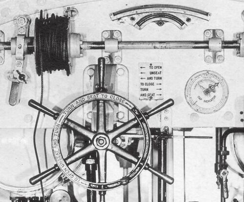
Detail of the port torpedo loading winch cable drum at the image top. To the left is the handle that allows the drum to be selected for use while leaving the starboard drum disengaged. There is a similar handle on the starboard cable drum to select or deselect that winch. The large hand wheel is used to open and close the rotating bow cap that acts at the tube muzzle door. At the top is an clinometer to show angles of list or roll the sub is experiencing. The dial on the right is a mechanical indicator for what position the bow cap is in. Behind the bow cap wheel to the left is a horizontal handle that is used to "seat and unseat" the bow cap into either the open or closed positions after it has been rotated. It appears to be chained into position.
U.S. Navy photo
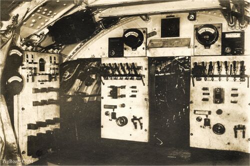
The control room of the C-1 looking aft. These are the electrical distribution panels used to control current flow from the generators to the battery, battery to the electric motors, and power distribution for assorted electrical equipment. You can see the starboard engine through the open doorway.
At the top right corner of the photo are control rods for the stern planes (right) and the rudder (left). The square panel below the rods, and a similar one on the left, are shaft rotation counters. They roll over like the odometer in a car. The large meters to the inside of the counters are volt meters. In the top left corner is a large dark object. After some deliberation and comparisons we believe this to be a Fessenden Oscillator.
A Fessenden oscillator is an electro-acoustic transducer invented by Reginald Fessenden, with development starting in 1912 at the Submarine Signal Company of Boston. It was the first successful acoustical echo ranging device. Similar in operating principle to a dynamic voice coil loudspeaker, it was an early kind of transducer, capable of creating underwater sounds and of picking up their echoes. (From Wikipedia)
The two panels on either side of the door to the engine room handle the electrical to and from the battery and or the motors/generators for each shaft.
For a sense of scale, an average person today, standing in this space, could read the cards on the sloping desk above the center opening to the engine compartment. Headroom would probably be a scant 6 feet.
When considered from the perspective of the 21st century, this equipment seems primitive and incredibly unsafe. No internal bulkheads, open knife switches, gasoline engines, etc. But when this boat was built in 1906, it was the absolute state of the art and very advanced. We have come a long way since then.
U.S. Navy photo
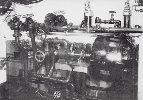
This is the C-1's trim pump. It wa located in the aft port corner of the control room. It was used to pump sea water from and to the forward and after trim tanks, auxiliary tanks, and bilges so that a proper fore and aft trim (balance) could be maintained.
U.S. Navy photo
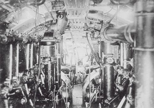
The C-1's engine room looking aft between the two Electric Boat/Craig gasoline engines. The 500 horsepower electrical motors for driving the submarine while submerged can be seen as two rounded objects just behind the engines. Fumes from the gasoline were a constant hazard to the crew. Even short-term exposure in an enclosed space can lead to headaches, nausea, and dizziness. It also causes a drunk-like stupor. In just a few years the Navy made a switch to diesel engines.
U.S. Navy photo
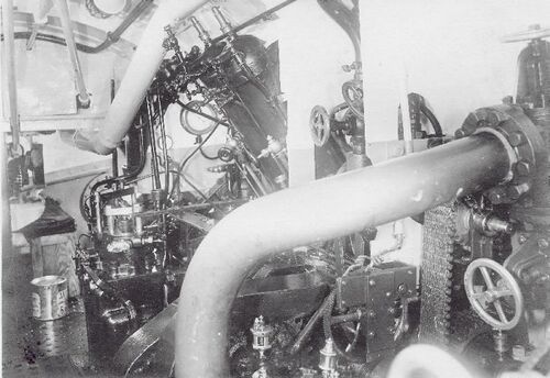
The C-1's engine room looking aft and to port over the top of the port clutch, above which may be the high-pressure air charging system.
U.S. Navy photo
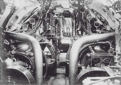
C-1's engine room looking forward. The camera is just aft of the clutches and 500 horsepower main electrical motors. The view between the gasoline engines gives a look into the control room and even the torpedo tube breech doors can be made out.
U.S. Navy photo
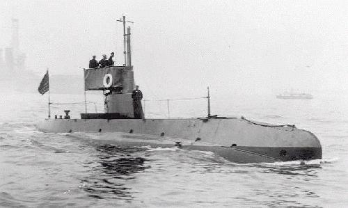
C-1 is shown here underway in what is likely the East River during the Naval Review at New York City, October 4, 1912. The ship in the background is likely the battleship USS Kearsarge (BB-5).
U.S. Navy photo
Page created by:
Ric Hedman & David Johnston
1999 - 2023 - PigBoats.COM©
Mountlake Terrace, WA, Norfolk, VA
webmaster at pigboats dot com
